Download
1 / 13
0 likes | 1 Views
Download the detailed product manual and technical specifications for the Kanex Nitrogen Filling Unit. Learn about features, usage instructions, safety guidelines, and maintenance tips.<br>

E N D
User’s Manual Nitrogen Filling Equipment KANADIA FYR FYTER PVT.LTD. User’s Manual Nitrogen Filling Equipment Model 2011 KANADIA FYR FYTER PVT LTD. A-110, KANARA BUSINESS CENTER. LAXMINAGAR, B/H EVEREST GARDEN APT.GHATKOPAR (E) MUMBAI-75. TEL: +91 22 2500 1288 TELE/FAX: +91 22 2500 3057 EMAIL: - info@kanexfire.com 1 | P a g e
User’s Manual Nitrogen Filling Equipment CONTENTS ?TITLE…………………………………………………………………………………………………………………………………………..1 ?INDEX………………………………………………………………………………………………………………………………………….2 1. GENERAL ADVICE .................................................................................................................................. 3 2. PRODUCT DESCRIPTION ....................................................................................................................... 4 2.1 Applications .................................................................................................................................. 4 2.2 Filling Procedure ........................................................................................................................... 4 2.3 Technical Details ........................................................................................................................... 5 3. SAFETY INSTRUCTIONS ......................................................................................................................... 6 4. BASIC ELEMENTS & FUNCTIONS .......................................................................................................... 7 4.1 Part List ......................................................................................................................................... 8 5. INSTALLATION .................................................................................................................................... 10 6. MAINTENANCE ................................................................................................................................... 11 6.1 Mechanical ................................................................................................................................. 11 6.1.1 Leakage ............................................................................................................................... 11 6.2 Electrical ..................................................................................................................................... 11 6.2.1 Power supply ....................................................................................................................... 11 6.2.2 Relay working ...................................................................................................................... 11 6.2.3 Solenoid working ................................................................................................................. 11 6.2.4 Pressure transmitter calibration ......................................................................................... 11 6.2.5 Controller calibration .......................................................................................................... 12 6.3 Instrumental ............................................................................................................................... 12 6.3.1 Machine Pressure gauge calibration ................................................................................... 12 6.3.2 Regulator pressure gauge calibration ................................................................................. 12 7. TROUBLESHOOTING ........................................................................................................................... 13 2 | P a g e
User’s Manual Nitrogen Filling Equipment 1.GENERAL ADVICE ?This User’s Manual will facilitate the secure and effective operation of the Nitrogen Filling Equipment. ?Therefore all users have to read and to have permanent access to this manual. ?All users MUST read this manual carefully before starting the Nitrogen Filling Equipment. ?IT is portable equipment easy to relocate. ?It is easy to use due to auto stop filling. ?Precise filling is possible with digital pressure signal & pressure transducer. ?Safety release is provided for safe operation. 3 | P a g e
User’s Manual Nitrogen Filling Equipment 2.PRODUCT DESCRIPTION 2.1 Applications ?The N2 Filling Equipment is used for charging nitrogen propellant to stored Pressure fire extinguishers. ?It is also a safety interface between the nitrogen store bottle and fire extinguisher by disabling overfilling of the extinguisher. At a filling pressure of more than 18 bars the safety valve opens and the pressure escapes to the environment. 2.2 Filling Procedure ?Supply the 230 v to the KANEX N2 filling equipment keep the main switch on while equipment is in use. ?Connect the equipment with N2 bottle via pressure regulator, inlet N2 pressure is shown on equipment, it does not exceed 20 kg per cm2. (In case of any mistake safety device provided in equipment will be released) ?Connect the FE bottle through flexible hose & filling gun, push the filling on button once the pressure reaches the set pressure (i.e. 15 kg per cm2) gas supply will automatically cut off, for filling the next bottle follow the same. ?Filling pressure can be set by high pressure set in digital pressure controller. ?If there is any leakage in outlet side connection or in FE, outlet pressure does not reach at set pressure equipment will not get auto stop, it will helps to identify leakage also. 4 | P a g e
User’s Manual Nitrogen Filling Equipment ?In case of any emergency push the emergency push button. 2.3 Technical Details 18 KG/cm2 Nitrogen Charging Pressure Machine Weight 9.98 KG Total Weight 16.78 KG Dimensions (L x W x H) 360mm x 260mm x 225 mm ?Manufacturer reserves the right to modify the design of the station and the Respective technical data without any prior notice. ?The Nitrogen Filling Equipment consists of following subassemblies : ? Case with pressure gauges. ? NRV with Ball valve with release output. ? Safety valve. ? Hose to connect nitrogen storage bottle. ? Hose to connect fire extinguisher. ? N2 Regulator 5 | P a g e
User’s Manual Nitrogen Filling Equipment 3.SAFETY INSTRUCTIONS ?When working with the Nitrogen Filling Station, the appropriate rules and safety regulations have to be obeyed. ?! NoticeThe User’s Manual must be accessible to all users of the station. ?Protect the filling station from humidity. ?! Warning Never use the filling station without pressure reducer at the nitrogen input. ? Use the station only if it is in good technical condition. The following symbols are used in this manual: ! Danger Immediate danger, which causes injury or death. ! Warning Possible dangerous situation, which can cause injuries or death. ! Caution Possible dangerous situation, which can cause small injuries or damages to property. ! Notice Possible damaging situation to product, property or environment. 6 | P a g e
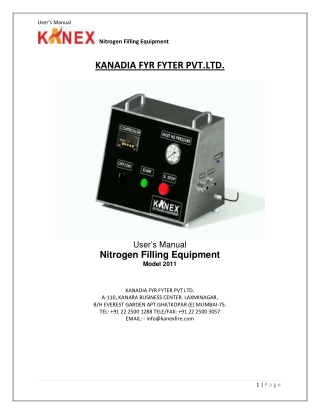
User’s Manual Nitrogen Filling Equipment 4.BASIC ELEMENTS & FUNCTIONS 7 | P a g e
User’s Manual Nitrogen Filling Equipment Inlet Pressure Gauge. Pressure Controller Display Emergency Stop Main Switch ON/OFF Filling Switch 4.1 Part List ?SS 304 body with good surface finish. ?Safety Valves. ?Pressure Gauge Range: 0 to 40 kg per cm2, SS dial, and glycerol filled, 2.5 " dial, rear connection panel mounted. ?S.S 304 Block with O-ring fitting SS pipe & SS Fitting. ?Pressure Transducer. ?Filling Gun with NRV & 2 Hoses ?Powers supply 230 V AC to 24V DC. ?Relay Card 2 Nos. ?Pressure meter & on/Off Switch. 8 | P a g e
User’s Manual Nitrogen Filling Equipment ?Start Push Button ( With green LED ) ?Emergency Switch. ?Solenoid Valve 24V DC. ?Handle. ?Rubber Pad ?Label Indicators. ?Electrical Wiring & Hardware. 9 | P a g e
User’s Manual Nitrogen Filling Equipment 5.INSTALLATION Placement ?The Nitrogen Filling Station Equipment must be placed on an even base, e. g. on a workbench, in order to prevent it from falling over when filling. Connections ?The black nitrogen input hose must be connected to the pressure reducer of a nitrogen storage bottle. ?This pressure reducer (available as an option) should be adjusted to a pressure which is lower than the pressure at which the safety valve opens. ?The pressure of the nitrogen storage bottle must be sufficient to fill the fire extinguishers properly. ?The Filling Gun with NRV must be connected to the fire extinguisher. Fitting adaptors are available from the manufacturer as optional items. Closeness Check ?Closeness and all functions of the Nitrogen Filling Station were checked by the Manufacturer before shipping. ! NoticeNevertheless it is required that the closeness of the station is checked again after installation. 10 | P a g e
User’s Manual Nitrogen Filling Equipment 6.MAINTENANCE 6.1 Mechanical 6.1.1 Leakage oTight the all connections like N2 inlet & Outlet hoses. oIf in case leakage found inside the machine assembly then checks the internal hose connection. If leakage found then tight that connection. oAlso check the leakage during Refill the Extinguisher. If leakage was found during refill the cylinder then machine take time for refill the extinguisher. oCheck leakage as per the given Maintains Schedule. 6.2 Electrical 6.2.1 Power supply oCheck the Power supply Single Phase 240 V AC. And do not use 3 Phase connection for the machine. 6.2.2 Relay working oPlease check the Relay mounting as per the maintenance Schedule. 6.2.3 Solenoid working oPlease check the Solenoid mounting as per the maintenance Schedule. 6.2.4 Pressure transmitter calibration oPressure transmitter need the calibration as per the maintenance Schedule. 11 | P a g e
User’s Manual Nitrogen Filling Equipment 6.2.5 Controller calibration oPressure transmitter need the calibration as per the maintenance Schedule. 6.3 Instrumental 6.3.1 Machine Pressure gauge calibration oPlease Calibrate the Pressure gauge as per the Maintains Plan. 6.3.2 Regulator pressure gauge calibration oPlease calibrate the N2 Regulator’s Pressure Gauges as per the Maintains Plan. 12 | P a g e
User’s Manual Nitrogen Filling Equipment 7.TROUBLESHOOTING SR NO PROBLEM POSSIBLE CAUSE REMEDY Replace storage bottle 1 Empty nitrogen storage bottle Input gauge doesn’t indicate pressure Pressure reducer not properly adjusted Adjust pressure reducer Replace input gauge Broken input gauge Adjust pressure reducer 2 Safety valve open Hissing noise Check connections Leaking connections 3 Closed filling valve Open the valve Filling pressure gauge doesn’t indicate pressure Replace output gauge Broken output gauge 13 | P a g e