Download

1 / 41
0 likes | 188 Views
Explore the realm of accuracy and precision with this enlightening talk on "Triangulation in Surveying." Start with an introduction to set the stage for a thorough comprehension of this essential surveying method. Examine practical uses for triangulation that make it essential for accurate land mapping and measuring. Discover the critical phases in the triangulation process, from reconnaissance to in-depth computations, to guarantee a comprehensive education. Gain a deeper understanding of surveying.

E N D
TRIANGULATION Surveying
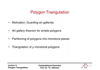
Table of content Introduction Applications of Triangulation Figures of Triangulation Reconnaissance in Triangulation Steps of Triangulation Calculations Conclusion
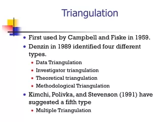
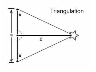
Triangulation is the process of determining the location of a point by measuring angles to it from known points at either end of a fixed baseline by using trigonometry. Introduction
George Everest Background William Lambton
Triangulation serves multiple Application across various fields and contexts. Here are a few important ones: • Surveying and Geodesy: In surveying and geodesy, triangulation is used to determine the positions of points on the Earth's surface. By measuring the angles between known points and an unknown point, and knowing the distances between the known points, the unknown point's position can be calculated using trigonometric principles
Navigation and GPS Navigation and GPS: Triangulation is employed in navigation systems such as GPS (Global Positioning System). GPS receivers receive signals from multiple satellites and use the time delays of the signals to determine the receiver's position through triangulation.
Astronomy: • Triangulation is used in astronomy to measure the distance to nearby stars. By observing a star's position from two different vantage points on Earth at different times, astronomers can calculate the star's distance based on the principles of triangulation.
Single Chain of Triangles • Simplest figure • Suitable for narrow strips • Quick • Cost Effective • Limited accuracy • Double Chain of Triangles • Suitable for Larger Areas • More complex • Better accuracy
Centered Polygons • Suitable for very large plain areas. • Time consuming • High accuracy • Very expensive and complex • Braced Quadrilaterals • Suited for hilly regions. • High accuracy
Reconnaissance in triangulation :- Reconnaissance is the inspection of the area to be covered by triangulation, and collection of relevant data. The accuracy and economy of triangulation greatly depends upon proper reconnaissance survey.
. The following are the objectives of reconnaissance in triangulation: To select suitable routes for access to the triangulation •To examine the area to be surveyed. •To determine the intervisibility of triangulation stations. •To collect information about the surrounding area, such as the presence of mountains, forests, and bodies of water.
The following instruments are used for reconnaissance in triangulation: •Small theodolite and sextant for measurement of angles. •Prismatic compass for measurement of bearings. •Steel tape. •Binoculars.
The benefits of conducting a reconnaissance in triangulation: •It helps to ensure that the triangulation survey is conducted effectively. •It helps to identify problems and challenges that may be encountered during the survey. •It helps to select the best possible location for triangulation stations.
Overall, reconnaissance is an essential part of any triangulation survey. By conducting a reconnaissance, the survey team can increase the chances of success and produce accurate results.
Steps of Triangulation Steps and techniques may vary depending on the surveying equipment, methodology, and the complexity of the survey area. Professional surveyors adhere to established standards and guidelines to ensure accurate and reliable triangulation results.
Sequence Determining Azimuth
There can be several factors that can cause error in triangulation. Here are some common factors… • INSTRUMENTAL ERROR Error associated with measuring instruments used in survey, such as theodolite or total station than can affect the accuracy of measurements. This error can include misalignment ,imperfect leveling ,reading error and faulty apparatus . • ATMOSPHERIC CONDITIONS Atmospheric condition such as ,refraction humidity temperature and air pressure can change the path of surveying rays, therefore it produce error in readings.
HUMAN ERROR ERROR INTRODUCED BY SURVEYORS DURING SURVEY AFFECTS THE MEASUREMENTS, THIS CAN INCLUDE MISREADINGS , MISPLACEMENT OF TARGET, AND MIIS IDENTIFICATION OF REFRENCE POINT • NATURAL OBSTRUCTIONS PRESENCE OF NATURAL OBSTRUCTIONS LIKE, TREES, UNEVEN TERAIN AND BUILDING CAN OBSTRUCT LIGHT OF SIGHT BETWEEN TO SURVEYING POINTS, IT CAN
EARTH CURVATURE EFFETS In large-scale survey , spheroidal effects of curvature of earth need to be considered. Neglecting these effects can cause of error, especially in large-scale survey.
They specify the point which upon which the instrument is to be focused upon. A combination of surface mark in conjunction with a permanent mark Mostly consist of a copper or bronze tablet cement into the ground. The details are stamped onto the plates • Signals Devices which are used to define the exact position of a station Measurements are taken via sighting onto the signals Two Main types: • Luminous Signals • Sun Signals: Sunlight rays known as heliotropes • Night Signals: Oil Lamps and Acetylene Lamps • Opaque Signals
OPAQUE SIGNALS They are used in the daytime to sight targets. • Pole Signals: Consists of a pile having Red and White stripes mounted on a tripod. Used for distances of up to 6 km • Target Signals: Consists of Two rectangular targets placed at right angles on a pole. Used for distances of up to 6 km • Beacon: Consists of a cloth tied around the three poles along with a flag on the top. Very useful when simultaneous observations are to be made.
Pole and Brush Signals: Consists of a Straight Pole of 2.5 metres with grass around the top making a cross on a heap of stones. • Stone Cairn: Consists of a signal on top of a heap of stones having a 3 m height. • Pole Targets • Target Set
Consider Triangle BCD Bearing from B to C = Back Bearing= Bearing from C to D = + 37 = Back bearing= Bearing from D to B = + 39 = 42 Back bearing = 222 Bearing from B to C= 222+ 103 = CORRECT!
Angle Adjustments: Check 1: ∑ Internal Angles = 360◦ In case of close figure other than triangle Check 2: Angle 1 + Angle 2 = Angle 6 + Angle 5 Angle 7 + Angle 8 = Angle 3 + Angle 4 Check 3: ∑ Internal Angles of Triangles = 180 ◦
Check 1 ∑ Internal Angles = 360◦ ∑ObservedInternalAngles=360◦00’17’ ERROR=+17” Errorperstation=17”/8
Check 2 Adjustment1 Angle 1+Angle2=Angle 6+Angle 5 70◦38’46’’+64◦58’18’’=77◦07’00’’+58◦30’01’’ 135◦37’04’’=135◦37’01’’ Error=03’’ Errorperangle=03’’/4 Since, L.H.S>R.H.S Subtract 01’’from2anglesinL.H.S Add 01’’inany1angleinR.H.S Adjustment2 Angle 8+Angle7=Angle 3+Angle 4 15◦40’40’’+28◦42’17’’=16◦41’13’’+27◦41’45’’ 44◦22’57’’=44◦22’58’’ Error= 01’’ Errorperangle=01’’/4 Since, L.H.S<R.H.S Subtract 01’’fromany1angleinR.H.S
CHECK 2 SECOND ITERATION OF CHECK 1
Check 2 ∑ Internal Angles of Triangles = 180 ◦ Consider triangleswithbaseline Triangle1 ∑InternalAngles ofTriangles=180◦ 8◦30’03”+15◦40’40”+ 105◦49’17”=180 ◦ 5OK Triangle2 ∑InternalAngles ofTriangles=180◦ 16◦41’12’+77◦07’00’+ 86◦11’48”=180◦ OK!
Co-ordinates computations Mean value of easting of A = [10518001.80’+10517507.25]÷ 2 =10517754.53’ Mean value of Northing of A= [3452312.56’+3453312.83]÷2 =3452812.695’
Mean value of easting of A = [10518001.80’+10517507.25]÷ 2 =10517754.53’ Mean value of Northing of A= [3452312.56’+3453312.83]÷2 =3452812.695’ Sample Footer Text
Conclusion: In conclusion, triangulation is a powerful technique that can be used to improve the accuracy of measurements. By measuring the same quantity from multiple different angles, we can reduce the effects of errors and biases. This is especially important in situations where it is difficult or impossible to make direct measurements. Triangulation has a wide range of applications, including surveying, navigation, and astronomy. It is a valuable tool for anyone who needs to make accurate measurements. Sample Footer Text
Thank You Sample Footer Text