Download
1 / 21
230 likes | 561 Views
A Study of Die Failure Mechanisms in Aluminum Extrusion. Authors: A.F.M Arif, A.K. Sheikh, S.Z. Quamar. Received: November 27, 2001 Published By: Journal of Materials Processing Technology, . Presented By: Brian B. Cherry Date: September 15, 2004 Class: Me 582, Professor Ed Red.

E N D
A Study of Die Failure Mechanisms in Aluminum Extrusion Authors: A.F.M Arif, A.K. Sheikh, S.Z. Quamar Received: November 27, 2001 Published By: Journal of Materials Processing Technology, Presented By: Brian B. Cherry Date: September 15, 2004 Class: Me 582, Professor Ed Red
OUTLINE • Introduction • Profile terminology / Die Profiles • Overall and class-wise break-up of failure modes • Type failure analysis per shape • Shape-wise breakdown of each failure mode • Conclusion / References
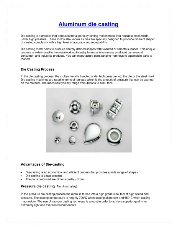
What is Extrusion? • A compression forming process in which the work metal is forced through a die opening to produce a desired cross-sectional shape. Relatively simple shapes… The bulk of aluminum profiles in the construction industry is produced through hot extrusion. Above is An extrusion press container. ..Or more complex shapes
Purpose of Technical Paper • Productivity, cost and quality are the overriding commercial factors. All three are related to the performance of the die. • Due to the high cost of a die based on material processing and fine tolerances, the most critical extrusion component is the die. • It is of considerable interest to focus on the relationship between die profiles and modes of die failure. • Testing: 616 dies, 17 various profiles, H-13 steel. • All billets are made of Al-6063. Bling..Bling!! Getting Rejected is Expensive And Embarrassing!!
OUTLINE • Introduction • Profile terminology / Die Profiles • Overall and class-wise break-up of failure modes • Various complexity failure analysis • Shape-wise breakdown of each failure mode • Conclusion / References
Die and Tooling Configuration Liner: Provides protection against thermal and mechanical stresses to the large and expensive container. Dummy Pad: Floating or fitted in front of the stem. It protects the life of the costly stem. Pressure Pad: Transfers the extrusion load from the bolster to the pressure plate and also guards against bolster deflection. Stem: It is fitted with the main ram to force the billet through the container. Die Bolster: Provides support to the die against collapse or fracture. Transfers the extrusion load from the die to the pressure ring. Die Ring: Holds the die, the feeder plate and the die backer together. Die and Tooling Configuration for hot extrusion of A1-6063. Die: Produces the extrusion shape.
Configuration of a Typical Die Configuration of a solid flat-face die.
Die Profiles Three types of die profiles Hollow Dies Solid Dies Semi-Hollow Dies Common features of die profiles
Die Profiles Sketches and die profiles used in the study.
OUTLINE • Introduction • Profile terminology / Die Profiles • Overall and class-wise break-up of failure modes • Various complexity failure analysis • Shape-wise breakdown of each failure mode • Conclusion / References
More Terminology • Crack: A visible, generally uneven fissure on the surface. • Break: Component is broken in two. • Chip off: A small piece is chipped off the surface. • Wash Out: Tiny but sig. craters or depressions cause by pitting or erosion. • Fracture: All fatigue failures. Cracking, chipping, breaking, surface fatigue, ect. • Wear: Gradual surface deterioration. • Deflection: Going out of shape, or sub-component owing to excessive plastic deformation. • Mixed: A combination of the above failures. • Mandrel: When the die has to be scrapped due to any failure in the mandrel. • Miscellaneous: Not specifically any of the above failures. Softening of the die or bearing
Class-Wise Breakup of Failure Modes 1. Nitriding oven failures cause sub-optimal hardening or heat treatment of the die. This makes the die and bearing softer than is needed. 1. With uneven and unsymmetrical sections, and existing maximum pressure and friction, the die (bearing) is most likely to plastically deform. 1. It should be pointed out that the replacement of the die takes place after cleaning and repair have occurred many times. The part produced simply is too far out of dimension. BPB=brush path broken CC=corner crack DB=die broken BCO=bearing chipping 1. In retrospect, brush paths are the most frequently repeated critical section and thus play a predominant role in fatigue failure. • Observations: • This supports intuitive reasoning. With large number sharp corners, projections and protrusions, slots and grooves, combination of thick and thin sections and general lack of symmetry, thermal and mechanical fatigue should be the primary failure mode. • Friction between hard aluminum-oxide layer on billet and iron-oxide layer on bearing causes hard wear problems. • Due to high temperatures and high extrusion speeds, plastice deformation should be expected. DimC=dimension change BWO=bearing wash-out Df=die deflected TBt=tongue bent/deflected BD=bearing damage DS=die softening
OUTLINE • Introduction • Profile terminology / Die Profiles • Overall and class-wise break-up of failure modes • Various complexity failure analysis • Shape-wise breakdown of each failure mode • Conclusion / References
Types of Failure per Die Type 1. Since semi-hollow dies are a cross between a hollow and a solid die, the even contribution of failure should be expected. • Due to lack of mandrel, forces at the die are far less wear critical. • This would indicate lower heat of friction deformation. 1. Since a large majority of the hollow dies were simple in geometry, there was far less of a contribution due to fracture.
OUTLINE • Introduction • Profile terminology / Die Profiles • Overall and class-wise break-up of failure modes • Various complexity failure analysis • Shape-wise breakdown of each failure mode • Conclusion / References
Shape-WiseBreakdown 1. Additional friction, temperatures and forces at the bearing inlet due to the presence of the mandrel would indicate the large proportion of deflection failures in hollow dies. • This confirms the previous conclusion that hollow dies fail primarily through wear. • Why are the solid and semi-hollow dies about the same even though one has a mandral and the other does not? 1. Since contributions of the hollow and semi-hollow dies are almost equally smalll, it shows that the predominant failure for solid dies is fatigue fracture.
OUTLINE • Introduction • Profile terminology / Die Profiles • Overall and class-wise break-up of failure modes • Various complexity failure analysis • Shape-wise breakdown of each failure mode • Conclusion / References
Conclusions • Testing supported the fact that the predominant failure for solid dies is fatigue fracture. • Hollow dies fail primarily by wear. • Additional friction, temperatures and forces at the bearing inlet due to the presence of the mandrel and re-weld chambers in hollow dies are the reason for the large proportion of deflection failures associated with hollow dies. • Mixed mode failure is prevalent with hollow dies. • Miscellaneous failure is predominant with solid dies. • Mandrel failure was obviously dominant in hollow dies.
Flaws in Technical Paper • Very few shape complexities were incorporated in the study. • Only one material type die, and one material type billet was tested. • Time line failure wasn’t included to incorporate the data with useful economics. • There variety of hollow dies used in the test didn’t have many details, and could bias the test data.
Refrences [8] M Gupta, R. Sikand, A.K. Gupta, Scr. Metallurgy Material, (1994), 30, 1343-1348. [9] M. C. Shaw and J. P. Avery, Forming limits – reliablilty, stress analysis and failure prevention methods in mechanical design, ASME Centennial Bound Volume, 297-303, (1980), Century Publications. [1] I. Flitta, T. Sheppard, Nature of friction in extrusion process and it’s effect on material flow, Materials Science and Technology, December (2002) 837-846. [2] Dinesh Damodaran, Rajiv Shivpuri, Prediction and control of part distortion during the hot extrusion of titanium alloys, Journal of Materials Processing Technology, 150 (2004) 70-75. [3] Zubear Ahmed Khan, Uday Chakkingal, P. Venugopal, Analysis of forming loads, microstructure development and mechanical property evolution during equal channel angular extrusion of a commercial grade aluminum alloy, Journal of Materials Processing Technology, 135 (2003) 59-67. [4] S. Malayappan, R. Narayanasamy, Barrelling of aluminum solid cylinders during cold upset forging with constraint at one end, Materials Science and Technology, June (2002) 507-511. [5] S. C. V. Lim, M. Gupta, Enhancing modulus and Ductility of Mg/SiC composite through judicious selection of extrusion temperature and heat treatment, Materials Science and Technology, August (2002) 803-808. [6] Bruce Chalmers, Physical Metallurgy, 321-327, 332,1959, John Wiley and Sons. [7] F. J. Humphreys, W. S. Miller, M. R. Djazeb, Materials Science and Technology, (1990), 6, 1157-1166.