Download
1 / 4
50 likes | 121 Views
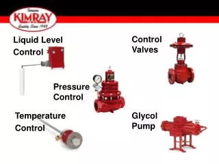
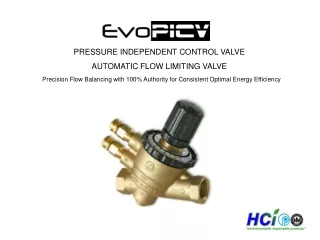
"Closed loop air pilot digital proportional control valve<br>Fully programmable with on-board diagnostics<br>Ability to set up offline<br>Multi-language menu option<br>Password protection option at first level functionality<br>Instant LED warning functions<br>Pressure output display<br>no gauge necessary<br>High-speed response"<br>For More Information visit on our website:- www.instronline.com<br>Our E-mail Address:-info@instronline.com <br>

E N D
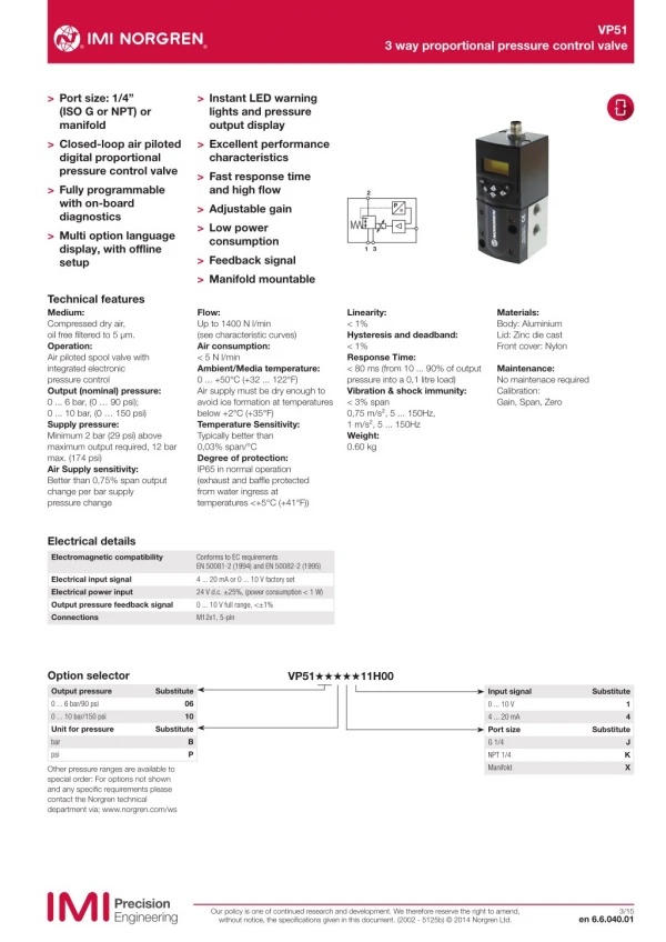
VP51 3 way proportional pressure control valve > Port size: 1/4” (ISO G or NPT) or manifold > Closed-loop air piloted digital proportional pressure control valve > Fully programmable with on-board diagnostics > Multi option language display, with offline setup > Instant LED warning lights and pressure output display > Excellent performance characteristics > Fast response time and high flow > Adjustable gain > Low power consumption > Feedback signal > Manifold mountable 2 P = 3 1 Technical features Medium: Compressed dry air, oil free filtered to 5 μm. Operation: Air piloted spool valve with integrated electronic pressure control Output (nominal) pressure: 0 ... 6 bar, (0 … 90 psi); 0 ... 10 bar, (0 … 150 psi) Supply pressure: Minimum 2 bar (29 psi) above maximum output required, 12 bar max. (174 psi) Air Supply sensitivity: Better than 0,75% span output change per bar supply pressure change Flow: Up to 1400 N l/min (see characteristic curves) Air consumption: < 5 N l/min Ambient/Media temperature: 0 ... +50°C (+32 ... 122°F) Air supply must be dry enough to avoid ice formation at temperatures below +2°C (+35°F) Temperature Sensitivity: Typically better than 0,03% span/°C Degree of protection: IP65 in normal operation (exhaust and baffle protected from water ingress at temperatures <+5°C (+41°F)) Linearity: < 1% Hysteresis and deadband: < 1% Response Time: < 80 ms (from 10 ... 90% of output pressure into a 0,1 litre load) Vibration & shock immunity: < 3% span 0,75 m/s², 5 ... 150Hz, 1 m/s², 5 ... 150Hz Weight: 0.60 kg Materials: Body: Aluminium Lid: Zinc die cast Front cover: Nylon Maintenance: No maintenace required Calibration: Gain, Span, Zero Electrical details Electromagnetic compatibility Conforms to EC requirements EN 50081-2 (1994) and EN 50082-2 (1995) Electrical input signal Electrical power input Output pressure feedback signal Connections 4 ... 20 mA or 0 ... 10 V factory set 24 V d.c. ±25%, (power consumption < 1 W) 0 ... 10 V full range, <±1% M12x1, 5-pin Option selector VP51˙˙˙˙˙11H00 Output pressure 0 ... 6 bar/90 psi 0 ... 10 bar/150 psi Unit for pressure bar psi Substitute Input signal 0 ... 10 V 4 ... 20 mA Port size G 1/4 NPT 1/4 Manifold Substitute 06 10 1 4 Substitute Substitute B P J K X Other pressure ranges are available to special order: For options not shown and any specific requirements please contact the Norgren technical department via; www.norgren.com/ws Our policy is one of continued research and development. We therefore reserve the right to amend, without notice, the specifications given in this document. (2002 - 5125b) © 2014 Norgren Ltd. 3/15 en 6.6.040.01
VP51 3 way proportional pressure control valve Connecting plugs Manifold mount assembly to ISO 2 sub base Elbow connector M12 x 1 Single manifold Page 4 0250081 Page 4 ZZ5M00 O-rings, flat seal and screws are included Electrical connector pin looking into the end of the instrument Pin-No. 1 2 3 4 5 Function +24 V d.c. supply 0 ... 10 V feedback Control signal (+VE) Common (supply signal and feedback return) Chassis 4 3 5 1 2 Characteristic curves (standard units) Forward flow characteristics (supply pressure 11 bar) 10 9 Relief flow characteristics (supply pressure 9 bar) bar 8 Outlet pressure 7 10 6 8 Outlet pressure 5 6 4 3 4 2 2 1 0 0 Nl/min 0 200 400 600 800 1000 0 200 400 600 800 1000 1200 1400 Flow Flow Valve built in user adjustable settings Setting Language Pressure units Password Protection Off-line Set up Options English, Español, Français, Italiano, German Bar, atm, kg/cm2, kPa, psi Protect against unau horised adjustment of he valve Set pressure between 0…10 Bar and Min – Max Signal Set pressure between 10…0 Bar and Min – Max Signal Change the time taken to ramp between two pressures. (Volume dependent) Allows the Integrator set le time to be set Amplitude of he di her on he spool Can be used for fine adjustment of output pressure at a given signal Can be used for fine adjustment of output pressure at a given signal Display feedback for user information. Shows power is present and can be set to flash when he output pressure is outside specified limits Normally off. Can be set to flash if the output pressure does not reach he required value within a specific time limit. Will also flash when he unit is set to local control. Valve output can be set using the arrow keys Option to resets he valve to the Factory default settings. Min Set up Max Set up Speed Setting Dynamic Response Dither Amp Min Set up Max Set up Monitor Output Green Indicator Red Indicator On-line Set up Monitor Set up Local Control Factory Defaults Manual Control Our policy is one of continued research and development. We therefore reserve the right to amend, without notice, the specifications given in this document. (2002 - 5125b) © 2014 Norgren Ltd. en 6.6.040.02 3/15
VP51 3 way proportional pressure control valve Basic dimensions Dimensions in mm Projection/First angle 1 23 20 31 8,5 M12 x 1 10 OK C 1 4 2 3 116,5 3 2 21 ø 4,2 ø 9 1 10,5 35 35 24,5 7 20 ø 27,5 20 46 36 55 50 1 M5 x 8 mm deep 23 VP51 with manifold surface 1 23 20 31 8,5 M12 x 1 10 OK C 1 4 2 3 10,5 116,5 3 2 ø 4,2 ø 9 10,5 24,5 35 1 10,5 7 10,5 ø 27,5 20 8,5 9 55 46 50 36 23 1 M5 x 8 mm deep Our policy is one of continued research and development. We therefore reserve the right to amend, without notice, the specifications given in this document. (2002 - 5125b) © 2014 Norgren Ltd. en 6.6.040.03 3/15
VP51 3 way proportional pressure control valve Manifold mount assembly to ISO 2 sub base included all seals and screws Connector Model: 0250081 Dimensions in mm Projection/First angle 1 2 11 39,5 27 44 13 M12 x 1 34,5 11 Ø 15 95 Connector, 90° M12 x 1, 5 pin, female, 5 m cable length, A coded 1 Two screws M4 x 50 mm deep to mount the VP50 onto the manifold 2 Four screws M6x16 mm deep to mount the manifold onto the iso subbase Warning These products are intended for use in industrial compressed air systems only. Do not use these products where pressures and temperatures can exceed those listed under »Technical features/data«. Before using these products with fluids other than those specified, for non-industrial applications, life-support systems or other applications not within published specifications, consult IMI NORGREN. The system designer is warned to consider the failure modes of all component parts used in fluid power systems and to provide adequate safeguards to prevent personal injury or damage to equipment in the event of such failure. System designers must provide a warning to end users in the system instructional manual if protection against a failure mode cannot be adequately provided. System designers and end users are cautioned to review specific warnings found in instruction sheets packed and shipped with these products. Through misuse, age, or malfunction, components used in fluid power systems can fail in various modes. Our policy is one of continued research and development. We therefore reserve the right to amend, without notice, the specifications given in this document. (2002 - 5125b) © 2014 Norgren Ltd. en 6.6.040.04 3/15