Download
1 / 5
50 likes | 71 Views
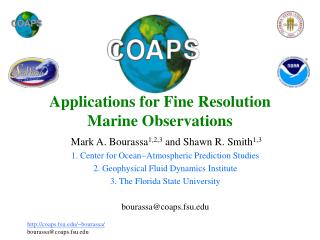
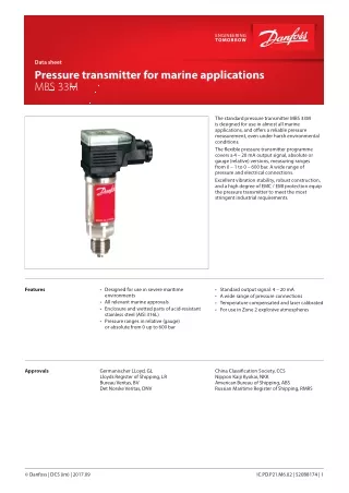
"The ship approved pressure transmitter MBS 33M is designed for use in almost all marine applications, and offers a reliable pressure measurement, even under harsh environmental conditions.<br>The flexible pressure transmitter programme is approved according to LR, DNV, GL, RINA, ABS, BV, NKK, PRS, MRS requirements and covers a 4-20 mA output signal, absolute and gauge (relative) versions, measuring ranges from 0-1 to 0-600 bar, plug and cable connections and a wide range of pressure connections.<br>Excellent vibration stability, robust construction, and a high degree of EMC/EMI protection equip the pressure transmitter to meet the most stringent marine requirements.<br>-- 4 - 20 mA output signal<br>-- Operating temperature -40 to 85u00b0 C<br>-- Measuring range 0 - 600 bar<br>-- A wide range of pressure connections available<br>-- Available with all relevant marine applications and designed to meet the strict demands on marine equipment<br>"<br>For More Information visit on our website:- www.instronline.com<br>Our E-mail Address:-info@instronline.com <br>

E N D
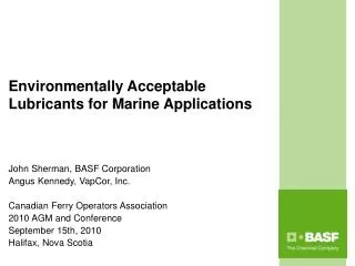
Data sheet Pressure transmitter for marine applications MBS 33M The standard pressure transmitter MBS 33M is designed for use in almost all marine applications, and offers a reliable pressure measurement, even under harsh environmental conditions. The flexible pressure transmitter programme covers a 4 – 20 mA output signal, absolute or gauge (relative) versions, measuring ranges from 0 – 1 to 0 – 600 bar. A wide range of pressure and electrical connections. Excellent vibration stability, robust construction, and a high degree of EMC / EMI protection equip the pressure transmitter to meet the most stringent industrial requirements. Features • Designed for use in severe maritime environments • All relevant marine approvals • Enclosure and wetted parts of acid-resistant stainless steel (AISI 316L) • Pressure ranges in relative (gauge) or absolute from 0 up to 600 bar • Standard output signal: 4 – 20 mA • A wide range of pressure connections • Temperature compensated and laser calibrated • For use in Zone 2 explosive atmospheres Approvals Germanischer LLoyd, GL Lloyds Register of Shipping, LR Bureau Veritas, BV Det Norske Veritas, DNV China Classification Society, CCS Nippon Kaiji Kyokai, NKK American Bureau of Shipping, ABS Russian Maritime Register of Shipping, RMRS © Danfoss | DCS (im) | 2017.09 IC.PD.P21.M6.02 | 520B8174 | 1
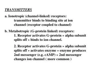
Data sheet | Pressure transmitter for marine applications, MBS 33M Technical data Performance (EN 60770) ≤ ± 0.5% FS (typ.) Accuracy (incl. non-linearity, hysteresis and repeatability) ≤ ± 1.0% FS (max.) Non-linearity BFSL (conformity) ≤ ± 0.2% FS Hysteresis and repeatability ≤ ± 0.1% FS ≤ ± 0.1% FS / 10K (typ.) Thermal zero point shift ≤ ± 0.2% FS / 10K (max.) ≤ ± 0.1% FS / 10K (typ.) Thermal sensitivity (span) shift ≤ ± 0.2% FS / 10K (max.) Response time Liquids with viscosity < 100 cSt < 4 ms Overload pressure (static) 6 × FS (max. 1500 bar) Burst pressure 6 × FS (max. 2000 bar) Durability, P: 10 – 90% FS > 10 × 106 cycles Electrical specifications Nom. output signal (short-circuit protected) 4 – 20 mA Supply voltage [UB] (polarity protected) 10 – 30 V DC Supply voltage dependency ≤ ± 0.1% FS / 10 V Current limitation (linear output signal up to 1.5 × rated range) 28 mA (typ.) Load [RL] (load connected to 0 V) RL ≤ (UB- 10 V) / 0.02 A [Ω] Environmental conditions Normal -40 – 85 °C Sensor temperature range ATEX Zone 2 -10 – 85 °C Media temperature range 115 - (0.35 × Ambient temp.) Ambient temperature range (depending on electrical connection) See page 5 Compensated temperature range 0 – 80 °C Transport / storage temperature range -50 – 85 °C EMC – Emission EN 61000-6-3 EMC – Immunity EN 61000-6-2 Insulation resistance > 100 MΩ at 100 V Mains frequency test Based on SEN 361503 15.9 mm-pp, 5 Hz – 25 Hz Sinusoidal IEC 60068-2-6 Vibration stability 20 g, 25 Hz – 2 kHz Random 7.5 grms , 5 Hz – 1 kHz 500 g / 1 ms IEC 60068-2-64 Shock IEC 60068-2-27 Shock resistance Free fall 1 m IEC 60068-2-32 Enclosure (depending on electrical connection) See page 5 2 | 520B8174 | IC.PD.P21.M6.02 © Danfoss | DCS (im) | 2017.09
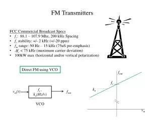
Data sheet | Pressure transmitter for marine applications, MBS 33M Technical data (continued) Explosive atmospheres Zone 2 applications EN60079-0; EN60079-15 When used in ATEX Zone 2 areas at temperatures <-10 °C the cable and plug must be protected against impact. Mechanical characteristics Wetted parts EN 10088-1; 1.4404 (AISI 316 L) Materials Enclosure EN 10088-1; 1.4404 (AISI 316 L) Electrical connections See page 5 Net weight (depending on pressure connection and electrical connection) 0.2 – 0.3 kg Ordering standard MBS 33M – 1 – Gasket / O-ring material No gasket Gasket, NBR -40 °C – 85 °C O-ring, NBR -40 °C – 85 °C 0 2 4 Measuring range 0 –1.0 bar 0 –1.6 bar 0 –2.5 bar 0 –4.0 bar 0 –6.0 bar 0 –10 bar 0 –16 bar 0 –25 bar 0 –40 bar 0 –60 bar 0 – 100 bar 0 – 160 bar 0 – 250 bar 0 – 400 bar 0 – 600 bar Pressure connection G ¼ A (EN 837) G ½ A (EN 837) ¼ – 18NPT ½ – 14NPT DIN 3852-E-G ¼; Gasket DIN 3869-14 NBR 1 0 1 2 1 4 1 6 1 8 2 0 2 2 2 4 2 6 2 8 3 0 3 2 3 4 3 6 3 8 A B 0 4 A B 0 8 A C 0 4 A C 0 8 G B 0 4 Electrical connection A9 Plug Pg 13.5 (EN175301-803-A) A3 Screened cable, 2 m A1 Plug Pg 9 (EN 175301-803-A) A6 Plug Pg 11 (EN 175301-803-A) Output signal 1 4 – 20 mA Non-standard build-up combinations may be selected. However, minimum order quantities may apply. Please contact your local Danfoss office for further information or request on other versions. Pressure reference Gauge (relative) Absolute 1 2 Prefered version IC.PD.P21.M6.02 | 520B8174 | 3 © Danfoss | DCS (im) | 2017.09
Data sheet | Pressure transmitter for marine applications, MBS 33M Dimensions / Combinations Type code A9 A3 A1 A6 EN175301-803-A,Pg13.5 2 m screened cable EN 175301-803-A, Pg 9 EN175301-803-A, Pg 11 34 38 39.5 39.5 DIN 3852-E-G ¼ Gasket: DIN 3869-14 NBR, Gasket G ¼ A (EN 837) G ½ A (EN 837) ¼ –18 NPT ½ – 14 NPT Type code AB04 AB08 AC04 AC08 GB04 Recommended torque 1) 2 – 3 turns after finger tightened 2 – 3 turns after finger tightened 30 – 35 Nm 30 – 35 Nm 30 – 35 Nm 1) Depends on different parameters as packing material, mating material, thread lubrication and pressure level 4 | 520B8174 | IC.PD.P21.M6.02 © Danfoss | DCS (im) | 2017.09
Electrical connections Type code, see page 4 A9 A3 A1 A6 EN 175301-803-A, Pg 13.5 EN 175301-803-A, Pg 9 EN 175301-803-A, Pg 11 2 m screened cable Ambient temperature -40 – 85 °C -30 – 85 °C -40 – 85 °C -40 – 85 °C Enclosure (IP protection fulfilled together with mating connector) IP65 IP67 IP65 IP65 Glass filled polyamid, PA 6.6 Poliolyfin cable with PE shirnkage tubing Glass filled polyamid, PA 6.6 Glass filled polyamid, PA 6.6 Material Pin1: + supply Pin 2: ÷ supply Pin 3: not used Brown wire: + supply Black wire: ÷ supply Red wire: not used Orange: not used Screen: not connected to MBS enclosure Pin 1: + supply Pin 2: ÷ supply Pin 3: not used Pin 1: + supply Pin 2: ÷ supply Pin 3: not used Electrical connection, 4 – 20 mA output (2 wire) Earth: Connected to MBS enclosure Earth: Connected to MBS enclosure Earth: Connected to MBS enclosure © Danfoss | DCS (im) | 2017.09 IC.PD.P21.M6.02 | 520B8174 | 5