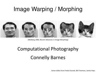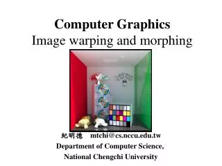
Morphing & Warping
Morphing & Warping. 2D Morphing. Involves 2 steps Image warping “get features to line up” Cross-dissolve “mix colors” (fade-in/fadeout transition) Related to texture mapping and grid deformation Texture mapping T(u,v) = (x,y,z), mapping specified by . vertex pairs. . u. v.

Morphing & Warping
E N D
Presentation Transcript
2D Morphing Involves 2 steps • Image warping “get features to line up” • Cross-dissolve “mix colors” (fade-in/fadeout transition) Related to texture mapping and grid deformation • Texture mapping T(u,v) = (x,y,z), mapping specified by vertex pairs. u v
What is texture mapping? • Texture mapping T(u,v) = (x,y,z), mapping specified by vertex pairs. • How does it work? Interpolation is used. Affine (think Bresenham), or perspective. Uh Oh!!!
Some details (Thanks, Wikipedia!) • Affine texture mapping directly interpolates a texture coordinate ua between two endpoints and u0 and u1: • ua = (1-a)u0 + au1 where 0 ≤ a ≤ 1 • A little openGL, if you’re curious • glTexParameteri(GL_TEXTURE_2D, GL_TEXTURE_MAG_FILTER, GL_NEAREST); • glTexParameteri(GL_TEXTURE_2D, GL_TEXTURE_MIN_FILTER, GL_LINEAR);
2D Morphing • Grid Deformation • G(x,y) = (u2 + v2, uv) (Mapping specified by equation) • Lack control for different parts of image F(u,v); • (Do we actually want the corners and edges of the image to move???)
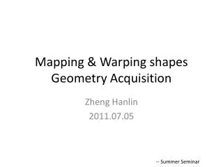
2 pass mesh Warping (Smythe 90) • Idea: use splines to specify curves on each image • get control of warping • Input • Source & destination images • 2D array of control points in source • 2D array of control pts in destination How to code new mesh into a changed image? Source Destination
To animate S D • Need to animate source grid to destination grid to produce intermediate grids I (could be multiple passes) • At each animation frame, need to generate intermediate image from S & I * Could use texture mapping, but the problem is we need to interpolate arbitrarily shaped polygons/triangles..
Steps • Fit curves through control points (e.g. Catmull-Rom splines) • 1st pass: match spans in x & interpolate • 2nd pass: match spans in y in intermediate image( from step 2) and interpolate • Match image to new grid (or images, if 2) • Cross dissolve (morph), if 2 different images Linear blend: Colorij = Δf ColorijD + (1 –Δf) ColorijS (pixel by pixel)
Steps For Each Frame in Animation for 2 different images 0 1 f … … time 0 n Source image Source grid Intermediate grid Intermediate image 1 Intermediateimage 2 Composite image Destinationgrid Destination image Warp source to grid Warp destination to grid Cij = Δf CijD + (1 –Δf) CijS
Magnification and Minification 1 2 3 4 5 1 2 3 4 5 Filter, e.g. gaussian 1 2 3 4 5 1 2 3 4 5 Averaging source pixels How to smooth out pixels?
Feature Based Image Metamorphisis (Beier and Neely, ’92) • Instead of using curves, use line-pairs to specify correspondence • Instead of 2 pass approach, 1 pass that calculates weighted contributions from each line pair to each pixel • Input: • Source image • Destination image • Line pairs PQS PQD
Step • For each frame between source S & destination D • Interpolate PQS & PQD to generate intermediate “destination shape” • Warp S to intermediate destination shape • Warp d to intermediate destination shape • Cross dissolve warped images • Save result as intermediate frame QS QI QD Still some problems (recall linear interpolation) – maybe use quaternion PS PI PD
Field Morphing For a Single Line Pair • Given P’Q’ in S, and PQ in D • Parameterize length as u:0 .. 1 over PQ and scaled over P’Q’ • Given some point X, distance v from PQ u = || X-P|| cos Ө/||Q-P|| (% distance from P, along PQ ) v = [(X – P) ┴(Q-P)]/||Q-P|| Where ┴(m) is defined -1/m … e.g. 1/(P-Q) V is the projection of of P-X onto the perpendicular vector V Q Q’ Is there an alternative math technique to get u and v? X v X’ =? u Ө P P’
Field Morphing For a Single Line Pair X’ = P’ + u• (Q’ – P’) + [v•┴(Q’-P’)] / ||Q’-P’|| Scaled u vector Unit vector along ┴ Q Q’ X v X’ u Ө P P’
Single Line Pair 80 80 Qs Pd Qd (30,50) 10 Ps 10 80 10 Source Destination Given the line pairs in the destination and source frames, what is the pixel in the source frame that corresponds to the point (30,50) in the destination frame?
u = (X-Pd) •(Qd-Pd) / |Qd-Pd|2 • u = (20,-30)•(70,0) / 702 • u = 1400/4900 = 2/7 • v = | (X-Pd) x (Qd-Pd) / |Qd-Pd|2 | • v =|(20,-30) x (70,0) / 702 | note: 2D cross product = determinant • v = 2100/4900 = 3/7
T = Qs - Ps=(0,70) • S = (Ty, - Tx) = (70,0) • X’ = Ps + uT + vS • X’ = (10,10) + 2/7 (0,70) + 3/7 (70,0) • X’ = (10,10) + (0,20) + (30,0) = (40,30)
Multiple Lines • Think Shepard’s algorithm • For point X in the source image, we calculate X’ for each of the line pairs • Then use a weighted sum to ultimately find the destination X’
The details • X’ is calculated from X and a weighted set of distances from X X’ = X +Σ DiWi / ( Σ Wi) , n = number of lines Di = Xi’ – X Wi = [ lengthiP/ (a+ disti )]b P =importance to line length. Increasing P increases the effect of longer lines b = how influence falls off with distance (0.5…2). What ifb=0? disti = distance from X to line i; as distance increases, weight decreases a = prevents division by zero, can also help with smoothing the lines themselves n n i = 1 i = 1
3D Morphing • Place link here
3D Morphing • Imagine you have two 3D meshes;how to morph between them? • Issues: • Getting a mapping between polygons of the 2 objects • Different numbers of polygons • Down sample or increase sampling? • Imagine you have two 3D volumes;how to morph between them?
Surface Morphing With Different Numbers of triangles • Use simplification (edge collapse techniques) to simplify correspondence • Make sure it is reversible/tracks changes • User needs to simplify vertices around features Specify points aroundkey features to preserve them Low Resolution, low vertex count High Resolution, high vertex count
Feature Based Volume Metamorphosis • Extension of idea of Beier and Neely • Instead of simple line pairs, element pairs • Elements have • “dimensionality”: can be a point, line, rectangular plane or volume (box) • spatial configuration: • Local coordinate system and origin • Scaling factor (features extent along local axes) • Beier and Neely method applied to get new mesh (handwaving..)
Another Method: Fourier Volume Mapping • Object volume must be described by a function • FT: integrate over [function*e-i2πft] • For each time step • Compute FFT of each volume’s function • Compute the weighted sum of the 2 FFTs • Undo the Fourier transform on the result The more “modes”, the closer to the actual function
Pluses and Minuses • Resolves correspondence issue (move out of cartesian space into frequency space) • A clean process but less than ideal results (better on some shapes than others) • No guarantee features will stay where they should
3D Morphing • Idea: input triangle mesh with different number of vertices • Use simplification to simplify correspondence problem