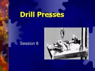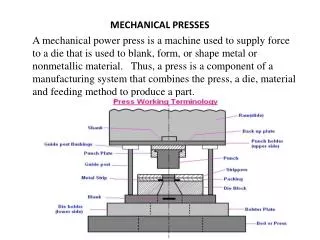
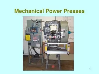
Mechanical Power Presses
Mechanical Power Presses. Mechanical power presses. OSHA 1910.217 is the vertical regulation OSHA 1910.212, general requirement; 1910.219 MPTA ANSI B11.1 - 1998 for best safety practices 350,000 in the U.S. Full revolution clutch since 1857 Part revolution clutch since 1927.

Mechanical Power Presses
E N D
Presentation Transcript
Mechanical power presses • OSHA 1910.217 is the vertical regulation • OSHA 1910.212, general requirement; 1910.219 MPTA • ANSI B11.1 - 1998 for best safety practices • 350,000 in the U.S. • Full revolution clutch since 1857 • Part revolution clutch since 1927
Capacity • 1/4 to bench-top to 5000 lbs. • Smaller one likely to be Gap (C) Frame • If inclinable, OBI, if not incliniable, OBS • Larger ones tend to be straight side frame • 4 columns from bed (bottom) to crown (top) • Distinctive features: flywheel, crankshaft, clutch, brake, ram (slide) goes up and down
Part revolution bench top press
Bench top press (cont’d) Overhead Guard Light Curtain
Full vs. Part Revolution Clutch? • Is an air line going to the clutch? • If yes, it’s a part revolution clutch press • If no, then look for an operating rod coming down the side of machine to identify it as a full revolution clutch
Part revolution clutch Air line going to clutch
Full revolution clutch Single Stroke Mechanism
Hydraulic Power Presses • OSHA 1910.212, general requirements, 1910.219 MPTA • ANSI B11.2 - 1995 for best safety practices
Hydraulic Press Light curtain Foot control
Power Press Brakes • OSHA 1910.212, general requirements, 1910.219 MPTA • ANSI B11.4 - 1993 for best safety practices
Modes of operation for mechanical power press • Inch: Short hops of ram used for setup, maintenance, but not for production • Single stroke: Often hand fed, sometimes with H.I.D. feeding. Safeguarding Devices most common • Continuous: Makes many cycles without stopping using an automatic feed & coil stock. Sging: Guards most common
Modes of Operation, Control Selector inch, single stroke, continuous Emergency stop button
Primary operations • Automatics or blankers • Coil stock with automatic feeds • Payoff reels or cradles to unwind • Continuous mode
Secondary operations? • Single-stroke mode of operation • Manually fed - one at a time • Often use Hands-in-Die Feeding • Hand feeding tools are the BSP • Cycle initiation can be hand or foot • Ergonomic issues if high repetition
Types of mechanical presses • Two general frame configurations • “C” frame • Used for maximum rated forces up 300 tons • Similar to “C” clamp in appearance • Three subcategories • OBI (Open Back Inclinable) • Gap Press (OBS) • Horn Press
Open Back Inclinable Press Hand operated inclining mechanism on OBI. Turning hand crank rotates screw to tilt press back to desired position.
Open Back Stationery Press Flywheel is located at the rear of the press frame on front-to-back presses, eliminating obstruction around the die frame.
General frame configurations (cont’d) • Straight side frame • Used on most presses that can develop a maximum rated tonnage of 20 tons or more • Consist of bed with a four corner post arrangement called uprights.
Part Revolution Straight-Side Press - Left Side View Main Drive Lifting Lug Air Surge Drive Air Releasing Brake Crown Dual Solenoid Valve Air Pressure Switch for Clutch/Brake Lubricator Air Pressure Switch for Counterbalance Operator’s Station Air Pressure-Gauge & Lubricator Assembly for Clutch/Brake Side Guard Bed Upright or Column Filter-Regulator-Gauge for Die Cushion
Air Counterbalance Tie Rod Nut Belts Sheave Tie Rod Main Gear Crankshaft Flywheel Air Friction Clutch Connection (Pitman) Side Adjusting Mechanism Cover Rotating Limit Switch Assembly Side (Ram) Knockout bracket Gib Knockout Rod Knockout Bar Run Buttons Control panel with Starter and Disconnect Switch Top-Stop Buttons Emergency-Stop Button Bolster Straight Side- Front View
Full Revolution - Left Side View Motor Cam and Limit Switch Motor Starter Drag Brake Disconnect Switch Control Box Knockout Knockout Bracket Inclining Mechanism Operator’s Station Slide (Ram) Frame (Body) Knockout Bar Side Barriers Leg
Full Revolution - Front View Belts Limit Switch Sheave Lifting Bolt Crankshaft Flywheel Clutch Area Connection (Pitman) Cover Side Adjusting Screw Lubricator Run Buttons (Two-Hand Trip) Die Clamp Gib Rear Barrier Air Cylinder (Solenoid Valve, & Filter-Regulator-Gauge and Lubricator Assembly Not Shown) Bolster Bed Leg Bolts Leg Tie Rod Foot Control
Types of mechanical power presses (cont’d) • Functional type • Operating characteristics • Full revolution clutch • Part revolution clutch • Electric motor is primary drive source • Motor drives press flywheel, which generates energy that’s applied by way of the crankshaft and ram to the lower dies.
Full revolution clutch • Uses keys, pins, or jaws to engage crankshaft to flywheel • Once engaged, clutch drags crankshaft through one complete revolution before it can be disengaged • Uses friction brake that is always applied to hold slide stationery when clutch is not engaged • Will not stop until it has completed one full stroke
Jaw type Striking plate on flywheel Rotary air seal Sliding sleeve with multiple engaging jaws Direct-acting pneumatic chamber
Friction Brake
Part revolution clutch • Engaged and disengaged at any point in slide • Engaged with air pressure/released with absence of air pressure • A friction brake that is air released and spring applied is used to stop and hold slide in position when clutch is not engaged • Can be stopped at any point in the stroke
Air line for clutch engagement. Engaged with air pressure, released with absence of air pressure. Part revolution clutch
Part revolution brake Air released and spring applied
Mechanical power presses and their controls - (full revolution clutch) • Machines using full revolution clutches • Will incorporate single stroke mechanism • Single stroke mechanism dependent on spring action • Springs will be compression type operating on a rod or guide within a hole or tube • Designed to prevent interleaving of spring coils in event of breakage
Single stroke mechanism Compression spring operating on a rod or guided within a hole or tube.
Methods of initiating press cycle • Foot pedals - treadle • Protected to prevent unintended operation from falling or moving objects. • Pad with nonslip contact area firmly attached to pedal • Pedal return springs will be compression type • If counterweights are provided, path of travel of weight will be enclosed • Enclose the weight’s path of travel to prevent interference with its movement
Foot treadle Canopy guard Removable foot pedal Treadle
Foot Control Manufactures Specifications Protection from unintended objects Applicable Safety Warnings Compression type spring
Hand operated levers • Will be equipped with a spring latch on the operating lever to prevent premature and accidental tripping • Operating levers, if provided are required for each operator, and require concurrent operation
Two-Hand trips • Protected against unintentional operation • Requires both hands, concurrent operation, and provided for all operators
Two-Hand Trips/Controls Note: Red stop button normally not present
Two-Hand Trip/Controls Prior Action Button Two Hand Control Emergency Stop Top Stop
Part revolution clutches • Machines using part revolution clutches • Clutch release and brake will be applied when external clutch engaging means is removed, deactivated or de-energized • Stop control • Red stop control, required at each station • Top stop, if provided, will be yellow • Stop control will override any other control
Part revolution clutches (cont’d) • Press stroking selector • A means of selecting off, inch, single stroke and continuous will be available. • Means capable of being supervised • Inch Operation • Designed to prevent exposure of worker’s hands by: • Requiring concurrent use of both hands • Being a single control protected against accidental actuation • Will not be used for production (ANSI)
Part revolution clutches (cont’d) • Multiple operating stations • Control station for each operator capable of being supervised • Continuous • Will be supervised, and require prior action or decision by the operator in addition to the selection of the continuous mode • Hand-foot selection • If provided, selection method for foot control will be separate from stroking selector • Will be supervised by employer