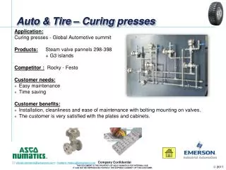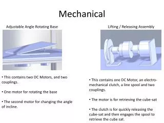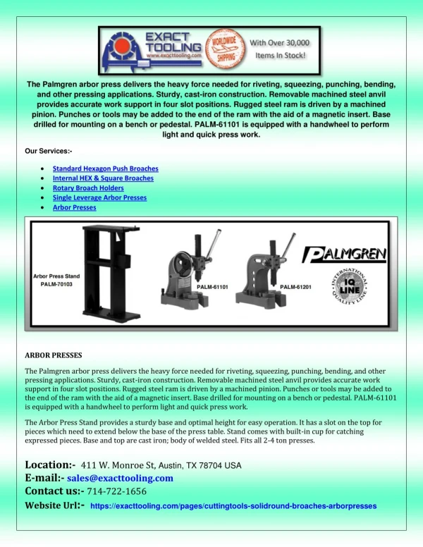
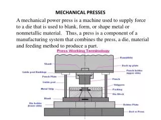
MECHANICAL PRESSES
MECHANICAL PRESSES . A mechanical power press is a machine used to supply force to a die that is used to blank, form, or shape metal or nonmetallic material. Thus, a press is a component of a manufacturing system that combines the press, a die, material and feeding method to produce a part. .

MECHANICAL PRESSES
E N D
Presentation Transcript
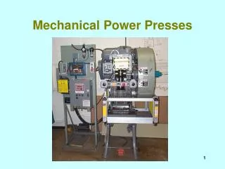
MECHANICAL PRESSES A mechanical power press is a machine used to supply force to a die that is used to blank, form, or shape metal or nonmetallic material. Thus, a press is a component of a manufacturing system that combines the press, a die, material and feeding method to produce a part.
TYPES OF PRESSES • There are over 300,000 presses in use in the United States and many more worldwide. • But most common types are • Open Back Inclinable (OBI) Gap Frame Press • Straight side Presses
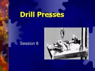
The open back inclined press • Figure illustrates one type of gap frame press. The principle feature of gap frame machines is the C-shaped opening. For this reason, gap frame presses are also referred to as C-frame presses. • In press force capacities up to approximately 250 tons (2,224 KN.) and larger, gap frame presses are less costly than a straight side press having the same force capacity and control features. In the 35 to 60-ton (311 to 534 KN) force range, they may cost approximately half as much as straight side press. • The C-shaped throat opening has the advantage of permitting access to the die from three sides. This enables press working operations to be carried out on the corners and sides of large sheets of material.
OBI Presses • The open back is also accessible for discharging finished parts and scrap as well as feeding stock. • The open accessibility from three sides facilitates quick die change with simple equipment. • The ease of access is also useful for trying out and repairing dies in the press.
Straight side Presses • Straight side presses derive their name from the vertical columns or uprights on either side of the machine. The columns together with the bed and crown form a strong housing for the crankshaft, slide and other mechanical components. • The housing or frame of most straight side presses is held together in compression by pre- stressed tie rods. Some straight side presses have solid frames. Generally a solid frame straight side press is less expensive than one having tie rods. However, tie rod presses are easier to ship disassembled and have better ability to withstand overloads. • Freedom from angular deflection under load is one reason for choosing a straight side rather than gap frame press for work involving close tolerance dies. The part dimensional accuracy and number of hits between necessary die maintenance often improves by a factor of three or more.
Straight side Press Constriction • the principle mechanical components of a straightside press having double end drive gears and two connections. The bed is the base of the machine. • The columns support the crown, and have gibs attached which guide the slide. The crankshaft end bearings may be contained in the columns or crown. • The crown serves many functions depending upon machine design. Typically, the clutch, brake, motor and flywheel mount on the crown of the press. The gears shown in Figure 2 may be open having only a safety guard designed to contain the gear in the event that it should fall off due to a failure such as a broken crankshaft. • In modern designs, the gears are fully enclosed and run in a bath of lubricant. Enclosing the gears in separate enclosures from the rest of the machine permits using a heavier viscosity lubricant than that used for other machine parts such as the bearings. The latter are often supplied from a recirculating lubricant system. The separate gear housing and lubricant bath system serves to lessen noise and insure long gear life. • The tie rods hold the housing assembly in compression. The pitman, connection, bolster and other parts have similar functions in both gap frame and straightside presses.
Types of Mechanical Press Drives • In non geared or direct drive presses as they are also known, the flywheel is mounted on the end of the crankshaft. • The flywheel is motor driven by means of a belt drive. • Directly driven presses are capable of much higher operating speeds than geared types. • Speeds range from under 100 strokes per minute to over 1,800 for short stroke high-speed operation.
Single Gear Reduction Presses • In single gear reduction presses, the flywheel is mounted on the backshaft and the power is then transmitted through a pinion to a main gear mounted on the crankshaft. Some single gear reduction presses have main gears mounted on both ends of the crankshaft, which is mounted on a pinion double end gear presses. Single gear reduction presses typically operate in the speed range of 16 to 200 strokes per minute (SPM).
Shut Height • The space available between the press bed or bolster and the slide or ram is called the shut height. It is always measured with the press shut or at bottom dead center. It may be specified as the vertical space between the ram and either the top of the bed or bolster as illustrated in Figure 9. • When a die must be put in an existing press, the distance from the top of the bolster to the bottom of the ram is the figure that should be used. This distance, specified with the screw adjustment at maximum and minimum values, determines the range of closed heights of the dies that will fit into the press. • At times, more shut height than that which can be accommodated with the press bolster in place is needed. Some shops have removed the bolster and fastened the die directly to the press bed. This is a poor practice. The bolster is needed to stiffen the bed and spread the load evenly.
Example of Shut Height Measurement • Example of shut height measurement taken (A) from ram to the bed, and (B) from ram to the bolster. Smith & Associates
Bed and Bolster • The bolster adds stiffness to the press bed and has tapped holes, or preferably T-slots, to permit the die to be fastened in the press. T-slots permit dies to be changed quickly and fastened in the press more securely than tapped holes. • The most important bolster measurement is the left-to-right and front-to-back dimensions. This determines the width and length of die that can be accommodated. • Occasionally, a shop will place a die in a press that overhangs the edges of the bolster. This is a very poor practice. The die is inadequately supported. In addition, safe die clamping to protect the operator may not be possible. • In some cases, the die shoe is designed to overhang the press bolster in an area where little or no work is done. This is done to balance the load to avoid ram tipping in progressive die operations. This practice is highly undesirable and greatly complicates legal machine guarding.
Moving Press Parts 1. The clutch which transmits energy from the flywheel to the crankshaft or eccentric drive, in some cases, through reduction gearing. 2. The brake used to stop the press and hold the slide and attached mechanism in place. 3. The flywheel, which stores the energy, supplied by the motor. 4. The motor which furnishes energy to the flywheel. 5. Gears where used to reduce the speed and increase the torque delivered by the flywheel through the clutch. 6. The pitman(s) or eccentric strap(s), which transmits the motion of the crankshaft or eccentric drive to the slide by means of the connection. 7. The connection, which connects the pitman(s) or eccentric strap(s) to the slide through a bearing. 8. The slide or ram to which the upper die is fastened: it is guided by gibs attached to the machine frame or housing. 9. The adjusting screw located at each slide connection point. 10. The counterbalance to counter balance the weight of the slide, upper die and attached linkage.
Upgrading Existing Presses • Older presses can often be upgraded for smoother, more reliable operation by retrofitting improved clutch and brake systems. In addition, the electrical controls, which may no longer meet current safety requirements, can be replaced. Usually, the most satisfactory way to retrofit the press is to install a complete new control package especially designed for the application. Such systems are available from several suppliers.
Press Capacity Factors • The press builder normally designs presses for specific applications taking into account three main criteria. These are: • 1. Component strength • 2. Flywheel energy • 3. Torque capacity
Component Strength • The physical strength of the various parts of the press must be sufficient to withstand long term cyclical loading at the rated force capacity of the machine. In addition, deflection must not exceed accepted design tolerances. Standard mechanical engineering formulas are used by press designers. The result is a robust machine that will provide decades of normal service at full capacity without failure. • Flywheel • The motor furnishes energy to the flywheel. Once the flywheel is up to speed and not being cycled, the motor need only supply enough energy to make up for frictional losses. The flywheel stores the energy until some is used to perform work.
Torque Capacity • The press must have the ability to take the energy of the flywheel, and transmit it through the clutch, gears (if a geared press), crankshaft, connection and slide to perform the required work without exceeding the safe working capacity of any component. The energy stored in the flywheel increases as the square of the flywheel rotational speed. Thus, presses having variable speed drives vary greatly in the amount of flywheel energy available depending upon the speed adjustment setting. • Reducing the flywheel speed reduces the total energy available. However, this does not reduce the press tonnage capacity. The tonnage capacity is based on the strength of the machine component parts • When the flywheel speed is reduced below its standard rating, the flywheel energy is reduced by the square of the speed reduction. Likewise, if the speed is increased, the flywheel energy is increased by the square of the speed increase. • The following calculations apply to a 60-ton (534 KN) nongeared press with a variable speed drive, which is adjustable from 50 to 200, strokes per minute. The 60 tons of force is available at a rated distance of 0.060-inch (1.5 mm) above bottom dead center at a rated speed of 100 strokes per minute. • Doubling the speed to 200 strokes per minute will result in four times the usable flywheel energy being stored. Because this press is designed with component strength and torque capacity of 60 tons, the additional stored flywheel energy is not usable. The press tonnage and torque capacity is the same. • If the speed is reduced by 50% to 50 strokes per minute, the flywheel energy is actually reduced by 75% because at one-half speed there is only one-fourth the energy left in the flywheel.
Press Construction Materials • The most common material for construction of crankshafts and other highly stressed parts such as pitmans and gears, is plain medium carbon steel; typically AISI-SAE 1045. However, alloy steels are employed for demanding applications. • Gray cast iron and iron alloys are used. Economy may be a factor in the choice of gray iron, especially in the case of older equipment. However, cast irons, especially iron alloys such as nodular iron damp vibration better than steel. For this reason, irons are used in the construction of many good quality high-speed press frames. • When parts made of cast irons and medium carbon steel are found to fail frequently in service, AISI-SAE 4140 chrome molybdenum alloy is a good choice. To a lesser extent, AISI-SAE 6150, a chrome vanadium alloy is used for highly stressed machine parts. • Both medium carbon and the popular alloy steels are readily cast or forged to shape. Properly done, welded repairs are generally successful in these materials.