Weighing Controller GM9907 Series
1.19k likes | 1.24k Views
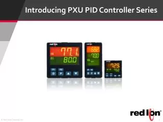
GM9907 is a general-purpose weighing controller series that is designed to control automatic packing machines. GM9907-LD with dual hoppers is for the double scale packing machine. The brand new GM9907-L2 has 5 models to complete different functionality(with/without hopper, bulk scale, valve port, PLC). This series can be widely used in the industries of feed, grain, seed, and chemical, and so on.<br><br>

Weighing Controller GM9907 Series
E N D
Presentation Transcript
GM9907-LD User’s Manual 110608030006 V03.01.08_1
©2020,Shenzhen General Measure Technology Co., Ltd. All rights reserved. Without Shenzhen General Measure Technology Co., Ltd.’s permission, any company or person have no responsibility to copy, transmit, transcribe or translate to any language version. Our company's products are under continually improvement and updating so we reserved the right to modify this manual at any time without notice. For this reason, please visit our website regularly to update newest information. Company Website http:// www.gmweighing.com Product Performance Standards: GB / T 7724-2008
Contents 1. Outline.........................................................................................................................- 1 - 1.1 Functions and Features..........................................................................................- 1 - 1.2 Front Panel Description.........................................................................................- 2 - 1.3 Rear Panel Description..........................................................................................- 3 - 1.4 Technical Specifications........................................................................................- 3 - 1.4.1 General specifications...............................................................................- 3 - 1.4.2Analog part.................................................................................................- 3 - 1.4.3 Digital part..................................................................................................- 4 - Installation...................................................................................................................- 5 - 2.1 General principle...................................................................................................- 5 - 2.2 Load Cell Connection............................................................................................- 5 - 2.3 I/O Module Port Connection.................................................................................- 5 - 2.4 Power Supply Connection.....................................................................................- 6 - 2.5 Serial Port Connection...........................................................................................- 6 - 2.6 Touch Screen Calibration......................................................................................- 7 - User Permission Description.......................................................................................- 9 - Menu............................................................................................................................- 9 - 4.1 Calibration........................................................................................................... - 11 - 4.2 Recipe Parameter.................................................................................................- 12 - 4.3 Weighing Parameter............................................................................................ - 16 - 4.4 Maintenance........................................................................................................ - 18 - 4.4.1 Scale Structure..........................................................................................- 19 - 4.4.2 Peripheral ON/OFF..................................................................................- 22 - Peripheral ON/OFF...........................................................................................- 22 - 4.4.3 Communication Setting...........................................................................- 23 - 4.4.4Auxiliary Logic Function.........................................................................- 24 - 4.4.5 Factory Reset............................................................................................- 28 - 4.4.6 Hardware Test...........................................................................................- 29 - 4.4.7 Display Style............................................................................................ - 29 - 4.5 Peripheral Parameter...........................................................................................- 30 - 4.6 Motor Parameter..................................................................................................- 34 - 4.7ACUM................................................................................................................. - 41 - 4.8 I/O Module.......................................................................................................... - 42 - 4.8.1 Output port & input port definition..........................................................- 44 - 4.9 Host mode............................................................................................................- 55 - Function Description.................................................................................................- 57 - 5.1 Setting the operating mode..................................................................................- 57 - 5.2 Batch....................................................................................................................- 58 - 5.3 Filling Level Control...........................................................................................- 58 - 5.3.1 Dual Supplement......................................................................................- 58 - 5.3.2 Single Supplement....................................................................................- 58 - 5.4 Quick Setup.........................................................................................................- 59 - 5.5 U disk update software........................................................................................- 59 - 5.5.1 Foreground update process...................................................................... - 59 - 5.5.2 Background update process......................................................................- 59 - 5.6 U disk update boot interface................................................................................- 59 - 2. 3. 4. 5.
5.7 Sewing control.....................................................................................................- 60 - 5.8 Discharge patting control.................................................................................... - 60 - 5.9Alarm function of filling and discharge overtime...............................................- 61 - 5.10Auxiliary pulse function....................................................................................- 61 - 5.11Adaptive function.............................................................................................. - 61 - 5.12 Hanger up control function............................................................................... - 62 - Serial port communication........................................................................................- 63 - 6.1 Printing method...................................................................................................- 63 - 6.1.1Auto Print................................................................................................. - 63 - 6.1.2 Total cumulative print.............................................................................. - 64 - 6.1.3 Cumulative print the recipe......................................................................- 66 - 6.1.4 User cumulative print...............................................................................- 66 - 6.2 Continuous mode.................................................................................................- 67 - 6.2.1 Continuous mode data frame format is as follows:................................. - 67 - 6.3 Modbus-RTU protocol........................................................................................ - 67 - 6.3.1 Function code and abnormal code........................................................... - 67 - 6.3.2 MODBUS transmission mode..................................................................- 68 - 6.3.3 MODBUS address assignment.................................................................- 68 - 6.4 Re-ContA/B protocol.......................................................................................... - 97 - Auto packaging process.............................................................................................- 98 - 7.1 Dual scale Net Weigher mode packaging........................................................... - 98 - 7.2 ScaleA Net Weigher mode packing..................................................................- 100 - 7.3 Scale B Net Weigher mode packing..................................................................- 101 - 7.4 Dual hopper dual clampe bagAB separate packing mode............................... - 102 - 7.5 Dual hopper dual clip bagAB Comb packing mode........................................- 103 - 7.6 Dual scale Gross Weigher mode packing..........................................................- 105 - 7.7 Dual scale Gross Weigher individual packing..................................................- 105 - 7.8 Bulk accumulation process................................................................................- 106 - 8. Motor Work Process....................................................................................................- 108 - 8.1 Motor Filling Portion.........................................................................................- 108 - 8.1.1 Step Motor Drive Filling........................................................................- 108 - 8.1.2 Motor Drive Filling................................................................................- 108 - 8.2 Motor lock Bag Portion.....................................................................................- 109 - 8.2.1 Step Motor Drive lock/unlock bag.........................................................- 109 - 8.2.2 Motor Drive Dual-Limit lock/unlock bag..............................................- 110 - 8.2.3 Motor Drive Single-Limit lock/unlock bag........................................... - 110 - 8.3 Motor Discharge Portion...................................................................................- 111 - 8.3.1 Step Motor Drive Discharge...................................................................- 111 - 8.3.2 Motor Drive Single-Limit Discharge.....................................................- 111 - 8.3.3 Motor Drive Dual-Limit Discharge........................................................- 112 - 8.3.4 Motor Drive Rotating Discharge............................................................- 112 - 8.4 Motor Debug Function......................................................................................- 113 - 9. Dimension (mm)..........................................................................................................- 114 - 6. 7.
GM9907-LD User’s Manual 1. Outline GM9907 bagging controller is a new weighing controller specially developed for automatic quantitative packing scale with double scale increment method.The controller adopts the English touch screen display interface, the operation is intuitive and simple;The new algorithm makes the weighing control faster and more accurate.USB interface and dual serial port make the device easier to system interconnection.Can be widely used in feed, chemical, food and other industries that need quantitative packaging equipment. 1.1 Functions and Features Full English display interface, make the operation more intuitive and easy Three optional weigher mode: Net Weigher mode , Gross Weigher mode and bulk scale. 28 ON/OFF input and output control (12 in /16 out); input and output port location can be customized. ON/OFF test functions, and convenient packaging weighers debugging Three levels speed automatic control filling, with optional slow jogging. It can store 40 kinds of recipes for different range of materials Convenient USB port to input and output of various types parameters fill control functions, convenient packing scale with the front filling device of controlMultiple digital filter function Automatic drop correction function Multiple digital filtering function Batch number setting function Patting bag function for packing powder materials Automatic zero tracking function Time / date function User permission identity settings Dual serial ports to connect with printer, computer, Secondary display. - 1 - GM9907-LD180101
GM9907-LD User’s Manual 1.2 Front Panel Description Interface Description: ① ① User info: Show user ID, recipe ID, system time, total ACUM and batch. ② ② Weight status: Weight value display, weight unit display, 9 digit display and output I/O module shortcut. ③ ③Shortcut:Fill,DISC,ZERO ,Adapt shortcuts for scaleA and scale B. ④ ④Packaging info: show currentACUM info, shortcut setting, batch and target value.。 ⑤Function parameters: Controller menu parameter and setting. ⑤ Debug interface description: ① ①Shortcut setting recipe paremeter: Can promptly setting recipe parameter, debug - 2 - GM9907-LD180101
GM9907-LD User’s Manual controller easliy. ② ②Packing history record: Can view the current packaging history data directly, easy to compare. Indicator light Description: Right one:power light; 1.3 Rear Panel Description 1.4 Technical Specifications 1.4.1 General specifications Power supply: DC24V Power filter: Included Operating temperature:-10~ Maximum humidity: 90% RH without dew Power consumption: about 15W Dimensions::190mm ×124mm ×48mm ~40℃ ℃ 1.4.2Analog part Load cell power supply: DC5V 125mA( Input impedance: 10MΩ Zero adjustment range:0.002~ Input sensitivity: 0.02uV/d Input range: 0.02~ ~ 15mV Conversion: Sigma- Delta (MAX) ) ~15mV( ( when load cell is 3mV/V) ) - 3 - GM9907-LD180101
GM9907-LD User’s Manual A/D Conversion rate: 120、 Non-linear: 0.01% F.S Gain drift: 10PPM/℃ The maximum display accuracy: 1/100000 、 240、 、480、 、960 Times/second 1.4.3 Digital part Display: 7 inch resistance touch screen Negative display: "— —" Overload Indication: weight over range/low signal of load cell Decimal point position: 5 options - 4 - GM9907-LD180101
GM9907-LD User’s Manual 2. Installation 2.1 General principle 1) )Make appropriate installation holes on the control box, ( size: 179(±1)mm ×113(±1) mm) 2) )Install the GM9907-LD into a control box. 3) )Remove the fixing plates on both sides of GM9907-LD, fix it with the fixing plates and lock them with M3*10 screws. 2.2 Load Cell Connection When you chose the six-wired load cells, you must bridge the SN+ with EX+ and bridge the SN- with EX-. EX+: Excitation+ EX-: Excitation- SN+: Sense+ SN-: Sense- SIG SIG+: : Signal+ SIG-: Signal- 2.3 I/O Module Port Connection GM9907-LD bagging controller controls 28 lines I/O (12 input and 16 output). It uses optoelectronic isolation technology to transfer data. The I/O signal input is low level effective, and the output is open-collector mode. The driving current can reach 500mA and the full load current is up to 3A, and Terminal connection is shown as below: - 5 - GM9907-LD180101
GM9907-LD User’s Manual I/O Module Input port diagram I/O Module output connection diagram I/O module value of GM9907 is user-defined to facilitate wiring and some special applications. Please refer to section 4.8 for I/O module. 2.4 Power Supply Connection GM9907 bagging controller use 24V DC power supply. The connection is shown in the figure below: Power terminal diagram 24V+ connect DC+,24V-connect DC-. Note:this product use 24V DC power supply,use 220VAC power supply will permanently damage the controller and cause danger. 2.5 Serial Port Connection GM9907-LD can provide two serial ports. It is depicted below.One for RS-232(Port - 6 - GM9907-LD180101
GM9907-LD User’s Manual TX、 RX、 GND) ; the other is RS-485, (Port A、 B、 GND) 。 serial ports support: MODBUS mode、Cont mode and Print format. Controller and computer connection diagram: Connection between GM9907-LD and a host computer (RS-232): Connection between GM9907-LD and a Host Computer(RS-485) 2.6 Touch Screen Calibration Fisrt use new controller or laid-aside for a long time need to calibrate touch screen, calibrate instruction: GM9907-LD power on, long press any point on the touch screen at the same time, system turn to touch screen calibrate interface, long press cursor position on touch screen, cursor position calibrate finish, after the interface displays the coordinates of this point, - 7 - GM9907-LD180101
GM9907-LD User’s Manual enter to next calibrate automatically. Follow cursor position changes long press accordingly, calibrate finish, and interface show 5 calibration point coordinates, enter to main interface automatically. If enter the calibration interface of the touch screen by mistake, press the "cancel" button in the lower right corner to exit the interface. - 8 - GM9907-LD180101
GM9907-LD User’s Manual 3. User Permission Description In order to prevent wrong operation causing GM9907-LD working improperly, it provides three rights (operators, administrators and system administrators) : System administrator can perform all operations (not open to users). The operator and administrator rights restrictions are as follows: Permission Operation Can check all the parameters. Can set recipt parameter’s value parameters and time parameters, I/O module test. Operator Can set batch in main menu, and the total quantity of dispatching. All operator privileges are available. Can calibration,start over/under, Free Fall correction and Adaptive function,set weight parameters,I/O module define,set language and time,correct computer mode parameter. Administrator Can modify opend Peripherals parameters Permission description: After the controller is power on, enter the permission selection interface, and enter the main interface after selecting the permission Operator have four login methord:Single operator login, multiple operator login, single operator keyword login, multiple operator keyword login. In【System Trial】 【Style setting】parameter,set the multi-operator login function ON/OFF, turn ON, set the number of operator logins. This is used to set the login mode for multiple operators. In 【System Trial】 【Style setting】 parameter, set login operator need keyword ON/OFF, turn ON, this is used to set whether a password is required for operator login. Multi-operators are set to 8, operator~operator 8 The operator cumulative data of single operator and multiple operators are merged into the user cumulative operator column in 【statistics】 Click the permission in the foreground, the logout pop-up window will pop up, you can logout the current permission to return to the permission selection interface. After the power is powered off and the system restarts, the rights are automatically deregistered. - 9 - GM9907-LD180101
GM9907-LD User’s Manual 4. Menu Click the menu to check or revise parameters.The menu is shown as follows. Click each parameter item to view and set the home parameter information under the current parameter item. Click top left of interface to exit the current interface and return to the previous page. Menu Parameter Parameter list Description Weight calibration Use weight to calibrate A material Calibration Calibration Use material to calibrate B material Calibration Zeroing range/Filter level setting Weighing parameters Set weight relevant parameters, such as zeroing range, stable parameters etc. Menu Input definition Input port definition. I/O Module Output definition Output port definition. Language setting Default English, Mandarin and English optional Time and language Time setting Screen time setting - 10 - GM9907-LD180101
GM9907-LD User’s Manual COM Master Master Write Data To Others Fill Gate Driver Fill Gate Driver parameters setting Clamper mode Clamper motor parameter setting Motor DISC Parameter DISC motor Parameter setting Scale Structure, Working Mode etc relevant setting Scale Structure Peripherals Select Peripherals Select ON/OFF setting Communication Serial ports, ethernet, print etc setting User Logic Program Aux.logic parameter, 6 group output logic parameter setting Maintenance Reset All parameters reset to factory setting Hardware Test To test all input and output connection. Display Style Display time setting Firmware Update Firmware Update System Info. Check calibration times and check code 4.1 Calibration Calibration should be done when a GM9907-LD controller is used at the first time, or the preset parameters can’t meet the user’s demand due to change any part of the weighing/bagging system. To enter calibration parameter need to input correct password as it is protected by password per International Standard. Calibration password can be modified by clicking any parameter requiring permission. (Initial password: 0000) Calibration interface, provide two kinds of calibration methods: weight calibration and material calibration.The calibration steps are as follows: Calibration parameter Item parameter Description 1.Unit Initial value: kg. Option: g/kg/t/lb. 2. Decimal point Initial value: 0.00. Option: 0~0.0000. 3 Minimum division Initial value: 1. Option: 1/2/5/10/20/50. - 11 - GM9907-LD180101
GM9907-LD User’s Manual Initial value:100.00; full capacity≤ division*100000 ≤minimum 4 Full capacity Calibration function is the calibration method using weights in site.The calibration steps for the weights of A and B are as follows Step 1 : According to the demand to choose units, decimal point, indexing value and other weighing parameters. Step 2:Empty the bucket and click 【Empty scale calibration】.This step is the zero point of calibration, requirements are: the bucket is empty, the scale body is stable Step 3:Put the weights on the weighing table, and when the weighing table is stable, click 【Weight Calibration】 , input the weight of the weights in the bullet frame, and click 【OK】to complete the calibration of the weights Test Weight Calibration Material calibration function is in the site is not convenient to use the weight calibration method. Steps as follow: Step1: Clear the scale table, wait for the mV to stabilize, then click 【 Empty scale calibration 】 .This step is to zero point of calibration, requirements are: bucket is empty, the scale body is stable. Step2:Click 【Manual Feeding】, then the feeding door opens, add some materials to the metering bucket, click 【Manual Feeding】again, close the feeding door.(Note: if the manual feeding time (Step2 time setting is manual feeding time) is not set to 0, the feeding door will be automatically closed after the manual feeding time is up). Step3:Click【Record】to display the gain millivolts after manual Feeding. Step4:Click【Discharge】.When the discharge door opens, the background will record the current relative millivolt.Weighing the discharge material with electronic scale and recording the data. Step5:Click【Calibrate】to input the weighing data and click OK.Material calibration is finished. A.B material calibration 4.2 Recipe Parameter Click the formula on the main interface to enter the 40 formula selection interface, which displays the formula number, name and target value. Click the recipe number button on the right to switch the recipe number. Click on each recipe bar to enter the corresponding recipe parameter interface. Click the upper left to return to the upper interface Recipe Item Parameter Description - 12 - GM9907-LD180101
GM9907-LD User’s Manual Packaging weight value setting. 1. TheAB target value is switched separately Optional on and off.when is on, the target values of A and B are set respectively; when is off, sets the total target value.Initial value: off. 2. Total target value “Individual Target Mode”When turn to off is valid In quantitative process, if the weighing value ≤ Near Zero Band, starts discharge delay timer. 3. Zero zone value a.A.Target value “Individual Target Mode”When turn on is valid In quantitative process, if the weighing value ≥ target value – Coarse Flow leading quantity, closing Coarse Flow fill. In quantitative process, if the weighing value ≥ target value – Medium Flow leading quantity, closing Medium Flow. In quantitative process, if the weighing value ≥target - free fall value, closing Fine Flow. b. Remain Co-Fi 4.Scale A Quantita tive value c. Remain Me-Fi d. Free Fall a.B.Target value “Individual Target Mode”When turn on is valid In quantitative process, if the weighing value ≥ target value – Coarse Flow leading quantity, closing Coarse Flow fill. In quantitative process, if the weighing value ≥ target value – Medium Flow leading quantity, closing Medium Flow. In quantitative process, if the weighing value ≥target - free fall value, closing Fine Flow. Used to set time - related parameters in the feeding process b. Remain Co-Fi 5.Scale B c. Remain Me-Fi d. Free Fall At the beginning of the quantification, the coarse feeding has been effective during this time to avoid overshooting without weight judgment Initial value:900; range:0~9999 (ms) 1.A.COMP. Inhibit Timer(Co-F) After the end of coarse feeding, in this period of time, in order to avoid overcharging without weight judgment, adding has been effective. Initial value:900; range:0~9999 (ms) Time paramete rs 2.A. COMP. Inhibit Timer(Me-F) After the end of the Medium feeding, in this period of time, in order to avoid overshoot without weight judgment, fine feeding has been effective. Initial value:900; range:0~9999 (ms) 3.A. COMP. Inhibit Timer(Fi-F) 4.B. COMP. Inhibit At the beginning of the quantification, the coarse - 13 - GM9907-LD180101
GM9907-LD User’s Manual Timer(Co-F) feeding has been effective during this time to avoid overshooting without weight judgment Initial value:900; range:0~9999 (ms) After the end of coarse feeding, in this period of time, in order to avoid overcharging without weight judgment, adding has been effective. Initial value:900; range:0~9999 (ms) 5.B. COMP. Inhibit Timer(Me-F) After the end of the Medium feeding, in this period of time, in order to avoid overshoot without weight judgment, fine feeding has been effective. Initial value:900; range:0~9999 (ms) 6.B. COMP. Inhibit Timer(Fi-F) In the with bucket mode, at the beginning of the quantitative process, after this delay time, the controller will conduct stability assessment and zero clearance (if it does not meet the conditions of zero clearance interval, then it will not be stable and zero clearance), and then start the feeding process; Without bucket mode, after the bag clamping is completed, after this delay time, the controller is stabilized and peeled Initial value:0.5; range:0.0~99.9 (s) 7. Filling Start Delay When the waiting mode is selected as " Result Waiting Timer ", fine feeding is turned off (or the over/under is turned on and the over/under alarm is over), and the setting is started. After this holding time, the setting is considered to be over and the next process is entered. Initial value:0.5; range:0.0~99.9 (s) 8.Result Waiting Timer In the discharge process, when the weight value of the scale bucket is less than the zero zone value, the delay is started, and the discharge signal is closed after the delay. Initial value:0.5; range:0.0~99.9 (s) 9. Discharge Delay Timer In the bucket combination mode, the discharge interval time value of balanceAand B. Initial value:0.5; range:0.0~99.9 (s) 10. DISC Interlock Timer 11. Hanger Up Delay In the no-bucket mode, the delay is executed after - 14 - GM9907-LD180101
GM9907-LD User’s Manual Timer the rise signal is issued. Initial value:0.0; range:0.0~99.9 (s) In no-bucket mode, the waiting delay is started after the end of the delay Initial value:5.0; range:0.0~99.9 (s) 12. Delay Timer Hanger Down After giving the bag clamping signal, after this delay, the controller determines that the bag clamping action is completed Initial value:0.5; range:0.0~99.9 (s) 13. Bag Locked Delay Timer After the discharge of Net weigher is finished, the unlock bag signal is output after this delay time. After the completion of the no-bucket mode setting (patting the bag), the unlock bag signal is output after this delay. Initial value:0.5; range:0.0~99.9 (s) 14. Pre-Delay Timer Unlock Bag Gross Weigher mode is effective. ScaleAdetects that the feeding level is effective after the bag is clamped, and then scale B also clamps the bag within this time. In this case, even if the feeding level is invalid, then scale B should also start feeding Initial value:4.0; range:0.0~99.9 (s) 15. Empty On Timer Supplement Over/Under alarm parameter setting 1. detection ON/OFF Over/Under ON/OFF. Judge over/under when in quantition process. ON/OFF. If set ON, the controller will stop if over or under. Input emergency stop and return to stop status, clear alarm information. Or input clearing alarm, press ENTER to procees quantitation. When the function of over/under is turned on, the time is started for over detection after the material feeding of each scale is finished. After the delay, the controller will stabilize and output over/under Initial value: 1.0. Range: 0 ~ 99.9s. (s) In value process, if the weighing value ≥ target value+ OverLimit Value, judged as OverLimit. Initial value: 0. In value process, if the weighing value ≤ target value- UnderLimit Value, judged as UnderLimit. 2.Over/Under pause ON/OFF Over/ Under 3.Over/Under detection Timer 4.Over value 5. Under value - 15 - GM9907-LD180101
GM9907-LD User’s Manual Initial value: 0. Supplement material judgement ON/OFF. ON: Slow jogging of material when under. (According to supplementary times). materials. 6.Supplement material ON/OFF OFF: Not supplement 7.Supplement material times If under, start to supplement materials as per setting times. Initial value: 1. Range: 1~99. 8.Effective supplement time Effective jogging time within a cycle period. Initial value: 0.5. Range: 0 ~ 99.9s. 9.Ineffective supplement time Ineffective jogging time within a cycle period. Initial value: 0.5. Range: 0 ~ 99.9s. For setting parameters automatically adjust the gap 1.Free fall correction ON/OFF 2 Correction sampling times correction basis. Initial value: 1. Range: 1~99. When this drop value exceeds the set range, it will not be included in the arithmetic average range. Initial value: 2.0. Range: 0.0 ~ 9.9(Percent of the target) 4.Free fall correction magnitude 50%, 25%. Initial value: 50%. Adaptive function, open the switch after the operation process automatically adjust the controller coarse, fine, increase the amount of advance and stop time. Optional, double speed, three speed. Initial value: off. (Note: 1. The fall correction and adaptive function cannot be turned on at the same time. If the adaptive function is enabled, the fall correction function must be turned off. 2. When the first scale adapts to start, it must ensure that the scale body is stable and the current weight is zero. The lower the grade, the faster the feeding speed, the relatively lower the accuracy. Initial value:3;range:1~5 When opened, the change value of coarse, medium and fine plus advance quantity will be updated to the value of quantitative parameter values cannot be updated Correct according to actual falling materials. Catch the average of free fall value and set as Free fall correctio n 3.Free fall correction range Every fall correction magnitude; Option: 100%, 1.Adaptive ON/OFF Adaptive 2.Adaptive Level 3.Parameters update ON/OFF quantitative parameter;When off, 4.3 Weighing Parameter - 16 - GM9907-LD180101
GM9907-LD User’s Manual In the menu interface, click the 【Weighing】 menu to enter the current parameter item to view and set the home parameter information. Parame ter Item parameter Description Zero Range Initial value: 50; range: 1~99 (Percentage of full scale) In the time of stability, the weight change range within this setting value is judged to be stable by the controller Stable Range initial value:2;range:0~99(d)。 Stable Timer initial value: 0.3;range:0.1~9.9(s) Weight values within this range, the controller automatically displays zero.Is 0, zero tracking is not performed. TrZero Range initial value:0;range:0~ TrZero Time initial value:2.0;range:0.1~ 1. Zero Range 2. Stable range/Timer 3. TrZero Range/Time ~9(d)。 ~99.9(s) On/off is optional. When "on", the controller will automatically perform zero clearing operation (the weight in the scale bucket meets the zero clearing range).Initial value: off. 4. PWR-ON Zero Weighin g paramet ers Wait Stable: After the fine feeding is closed, the weight is stable and the value setting process is completed Time Delay: After the slow feeding is closed, the valuing process is completed after the fixed value holding time initial value:Wait Stable 5. Result Check Mode The number of times the packaging process is completed and a zero clearance is carried out.When entering the running state, the controller is not reset during the first packaging process. initial value:0;range:0~ (Note: This parameter is only valid for Net Weigher mode and bulk scale mode) 6. PreFill Zero Interval ~99. Optional on/off;Set to "on", manual discharge weight value is included in the cumulative value.Initial value: (Note: This parameter is only valid for Net Weigher mode and bulk scale mode) 7. Manual DISC To ACUM 8.A/D Sample Rate A/D Sample Rate,120 times/s, 240 times/s, 480 - 17 - GM9907-LD180101
GM9907-LD User’s Manual times/s, 960 times/s optional, initial value: 240 times/s. AD Digital filtering parameters: 0: no filtering;9: The filtering effect is strongest.Initial value: 7.Range: 0 ~ 9 9. D-Filter Strength secondary filtering based on digital filtering. Initial value: 0.Range: 0 ~ 9 10. Vib-Filter In the packaging process, whether to carry out filtering operation switch and set "on", the following parameters are valid;Initial value: on. Dynamic Filter Filtering parameters in the feeding process: 9: The strongest filtering effect. Initial value: 4; Range: 0 ~ 9. 11. Dynam ic Filter parame ters Filling Filter Result Check Filter Filtering parameters in the feeding process: 9: The strongest filtering effect. Initial value:7;Range:0~ ~9 Filtering parameters in the discharge process: 9: The strongest filtering effect Initial value:3;Range:0~ Discharge Filter ~9。 Optional on/off;Set to "on", the weight of the controller is fixed at the weight of the fixed value after the fixed value, and the real-time weight will be displayed when the weight of the discharge (loose bag) is lower than half of the target value.Initial value: off. 12. Result Hold 4.4 Maintenance - 18 - GM9907-LD180101
GM9907-LD User’s Manual 4.4.1 Scale Structure Item parameter Description a. Scale structure Net Weigher;Net Weigher / Gross Weigher / bulk scale mode b. Working mode Net Weigher is optional: AB double scale, alone A scale, alone B scale, double clip bag AB independent, d double clip bag AB combination;Initial value: AB double scale. Single feeding/combination feeding is optional; Initial value: Combination feeding. Combination feeding: fast feeding large, medium and small feeding port at the same time; Add medium and small feeding port at the same time feeding; Slow time small feeding port feeding. Separate feeding: fast and large feeding port feeding; Add when the feeding port feeding; Slow time small feeding port feeding. c. Filling control method d. Filling mode 0Air Drived mode;1 Step motor feeding 2 motor mode e. Clamper Driver 2. Net Weigher parameter setting 0Air Drived mode;1 Step motor;2、Normal Motor(Two Pos. Signal);3 Normal Motor(One Pos. Signal) Default value:0Air Drived 0Air Drived mode;1 Step motor;2 Normal Motor(One Pos. Signal) 3 Normal Motor(Two Pos. Signal);4 Normal Motor Rotating Default value:0Air Drived f. Discharge mode g. Manual Unlock Bag Optional on/off; Set to "on", in operation, need to manually control unlock bag. Initial value: off. Net Weigher mode is effective. The Hopper Capacity is weighed and the number of discharging times is calculated with the target value. h. Hopper Capacity In Net Weigher mode stop state, set to "on", manual unloading, the bag clamping signal switch should be judged, after the bag clamping is allowed to discharge.Initial value: off. Note: In the dual bucket and double clip bagAB independent and double bucket and double clip bagAB combination mode, manual unloading can judge the loose bag switch is on. During i. Bag Lock Required (Manual DISC) - 19 - GM9907-LD180101
GM9907-LD User’s Manual unloading, the clip bag status of scaleAand scale B will be detected respectively. a. Scale structure Gross Weigher;Net Weigher / Gross Weigher / bulk scale mode b. Working mode SingleA scale Gross Weigher, Single B scale Gross Weigher,A/B NoneHopper,A+B NoneHopper Single feeding/combination feeding is optional; Initial value: Combination feeding. Combination feeding: fast feeding large, medium and small feeding port at the same time; Add medium and small feeding port at the same time feeding; Slow time small feeding port feeding. Separate feeding: fast and large feeding port feeding; Add when the feeding port feeding; Slow time small feeding port feeding. c. Filling control method d. Filling mode 0Air Drived mode;1 Step motor feeding;2 Motor mode e. Clamper Driver 0Air Drived;1 Step motor;2 Normal Motor(Two Pos. Signal); 3 Normal Motor(One Pos. Signal) Default value:0Air Drived 2. Gross Weigher parameter setting Optional on/off; Set to "on", in operation, need to manually control loose bag.(Note: in the combinatorial mode ofAB without bucket, this parameter and the allowable loose bag switch in operation cannot be opened at the same time) Initial value: off. f. Manual Unlock Bag Gross/net weight packaging is optional;. In the net weight packaging mode, the tare weight is cleared at the beginning of quantification, and the quantitative packaging process is carried out with the net weight value. Initial value: net weight packing. g. G/N Packing Loosen bag mode optional: close, simultaneously loose bag normal mode, simultaneously loose bag fast mode.Initial value: Off. (Note: Only the combinatorial mode without bucket AB has this parameter) 1. Loose bag normal mode For example, one scale has finished feeding another scale has not h. Unclock Bag(None Hopper) - 20 - GM9907-LD180101
GM9907-LD User’s Manual finished feeding, waiting for the completion of another scale at the same time after the two loose bags. If a scale has finished feeding, the other scale is not in the bag (feeding) state, then do not wait for another scale, this scale directly loose bag. 2. loose bag fast mode In this mode, scale A is placed in front of scale B.For example, scale A will directly loosen the bag without judging whether B is finished after feeding. After the completion of feeding, B shall judge whether A is in the state of bag clamping (feeding). If A is feeding, B shall wait for A to loosen the bag after the completion of feeding.If A is not feeding, B will loosen the bag without waiting. Optional on/off; Set to "on", no bucket mode, feeding, need to manually control loose bag. Initial value: off. (Note: In the combinatorial mode of AB without bucket, this parameter and manual loose bag switch cannot be opened at the same time.) i. Disable Unlock Bag When Running a. Scale structure Net Weigher;Net Weigher / Gross Weigher / bulk scale mode b. Working mode Bulk is optional: Bulk single hopper A , Bulk single hopper B, Bulk scale AB independent, Bulk scaleAB Interlock; Initial value: Bulk scaleAB independent. Single feeding/combination feeding is optional; Initial value: Combination feeding. Combination feeding: fast feeding large, medium and small feeding port at the same time; Add medium and small feeding port at the same time feeding; Slow time small feeding port feeding. Separate feeding: fast and large feeding port feeding; Add when the feeding port feeding; Slow time small feeding port feeding. 3.Bulk scale mode paramet er setting c. Filling control method d. Filling mode 0Air Drived mode;1 Step motor feeding;2 Motor mode 0Air Drived mode;1 Step motor;2 Normal Motor(One Pos. Signal) 3 Normal Motor(Two Pos. Signal);4 Normal Motor Rotating Default value:0Air Drived e. Discharge mode - 21 - GM9907-LD180101
GM9907-LD User’s Manual The bucket mode is effective. The Hopper Capacity is weighed and the number of discharging times is calculated with the target value. f. Hopper Capacity g.Flow window length Sampled times is used to calculate the current flow value. Initial value:5;range:1~ ~6. 4.4.2 Peripheral ON/OFF This parameter sets the switch of instrument peripheral. If set on, peripheral parameters of the main interface can be set. Refer to Chapter 4.4 for specific peripheral parameters. Paramete r Item parameter Description Bag mode selection: Initial value: Do not pat the bag. Optional: Net Weigher mode: no patting bag/patting bag after fixed value is optional Gross Weigher mode: no patting bag/after fixed value beat bag/feeding in the bag/feeding in the bag after fixed value all patting bag Pat bag parameter Whether to turn on the function of the sewing machine.On and OFF are optional. When turn to ON, the peripheral device can start to sew the bag, and the parameters of the sew machine can be set. Sewing Device Peripheral ON/OFF When turn on the conveyor function.On and OFF are optional. When turn ON, the external device starts the function of conveyor and the parameters of conveyor can be set. Conveyor Whether to enable the coding function.On and off are optional. When on, the peripheral starts coding function, and the coding parameters can be set. Coding Device Whether to open the discharge shaking switch.Optional on and off. When on, the external device opens the discharge shaking function, and the DISC Shaking parameters can be set. DISC Shaking Switch - 22 - GM9907-LD180101
GM9907-LD User’s Manual Whether to enable auxiliary pulse function.On and off are optional. When on, this function is enabled by peripherals and auxiliary pulse parameters can be set. Auxiliary Pulse Switch Whether to turn on the Fill&DISC Monitor.On and off are optional. When on, the peripheral enables this function, and the timeout alarm parameter can be set. Fill&DISC Monitor 4.4.3 Communication Setting GM9907 provides two serial communication interface; See Section 2.5 for the definition of serial port output; Correct setting of port parameters can be used for communication. Communciation parameters Item Parameters Description 1. ID No. Initial value: 1. Option: 1~99. Initial value:Modbus-RTU.Modbus-RTU / Print / Continuous mode/Re-ContA/Re-ContB 2. Communication mode Serial port parameters (Serial port 1. RS232 Serial port 2. RS485) Initial value:38400; 9600/19200/38400/57600/115200 3. Baud rate Initial value: 8-E-1 (8 data bits - even parity -1 stop bit). Option: 8-E-1/8-N-1/7-E-1/7-N-1. 4. Data format Modbus communication mode: Initial value: AB-CD (High word first). Option: AB-CD (High word first) / CD-AB (Low word first). 5. Modbus Hi-Lo 1. Communication Mode Fixed: Modbus-TCP Initial valueAB-CD. ahead ) )/ CD-AB( Range:AB-CD( (Low word first) ( Hi 2.modbus-TCP Hi-Lo ) 3. port number Initial value 502. Range 1~65535 Ethernet parameters Initial value 192 Range 0~255 Initial value 168 Range 0~255 4.IP Initial value 101 Range 0~255 Initial value 246 Range 0~255 5.MAC BC.66.41.9x.xx.xx - 23 - GM9907-LD180101
GM9907-LD User’s Manual Optional on/off;When "Open" is selected, the packaging result will be automatically printed out each time the packaging is completed (the serial port is required to select "Print") Initial value: off. 1. Auto Print Print Initial value: 24 columns to print; 24 columns to print /32 columns to print 2. Printer Format 3. Printing Language Initial value: Chinese print; Chinese/English printing is optional 4. Print Empyt Line Nos. Number of lines of paper after printing, initial value: 3; Optional 0 ~ 9. 4.4.4Auxiliary Logic Function Auxiliary logic programming function, can define up to 6 sets of auxiliary logic trigger signals, and can set the effective time and output port after the auxiliary logic signal is triggered, can configure simple logic signal output for the control of other auxiliary equipment, 6 sets of auxiliary logic signals can also control each other. Auxiliary logic programming parameter 1~6 OFF(default) Delay on Delay to disconnect Delay on Delay to disconnect Invalid-valid Jump trigger Valid-Invalid jump trigger After any one of the 1-12 channels is set as the trigger signal, the input port will be fixed as the trigger signal. After setting the trigger condition, the current weight value is compared with the set weight threshold, and the output is triggered when the condition is met. If any path in the input port from 1 to 12 is set as the trigger signal, the input can be either the trigger Parameter Descriptions 1. Logic type (1~6) Select the type of auxiliary logic programming signal based on the logic to be implemented. Custom trigger input (default) 2.Logic ( trigger signal 1~6 >=or<=weight trigger ) IN port 1~12 - 24 - GM9907-LD180101
GM9907-LD User’s Manual signal or the function signal of the input port. After the trigger signal is set as "an internal function signal", the output is triggered according to the function signal. Initial value:undefined Select the input port of the ON/OFF corresponding to the function signal. The input port "0 undefined" means that the function is not defined. Initial value:undefined Select the output port of the ON/OFF corresponding to the function signal. The output port "0 undefined" means that the function is not defined. Initial value: 0.0; Range: 0.0~99.9 After the trigger signal is valid, the logic output signal is valid only after the delay. I/O Module output define 3.Trigger input port IN1~12 4.Output signal port OUT1~16 5.Delay connect time Unit:s 6.Delay disconnect time Initial value: 0.0; Range: 0.0~99.9 After the trigger signal is invalid, the logic output signal will be invalid after the delay. Unit:s Initial value: 0.0; Range: 0.0~99.9 The duration after the logic output signal outputs a valid signal becomes invalid at the end of time. Initial value:0.0; Range:0.0~Maximum range Set the weight value, compare the current weight with the threshold weight, and trigger when the weight value trigger condition is met.(valid when the trigger signal selects ">= or <= weight value") 7.Output valid time Unit:s 8.Logic threshold weight Unit:kg Delay ON ● When selected to delay connection 【By Trigger Function】, the operation is as follows: 1. Set parameters and I/O Module: type select 【delay on】, Function】 trigger input port is defined as "1" (I/O Module input port 1 is shown as "auxiliary logic trigger input 1"), logic output port is defined as "1" (I/O Module output port 1 is shown as "auxiliary logic output 1"), set【Logic6 Delay ON timer】for 2 seconds. 2. Operation: trigger signal input 1 valid, start the delay connection time, and continue to be valid until the delay connection time 2s ends, the logic output signal port 1 outputs valid, until the trigger signal input 1 is invalid, the logic output signal port 1 also becomes invalid. Refer to diagram below ●When selected to delay connection 【Input Port 1-12】, operation is as follows: 1. Set parameters and I/O Module: trigger signal choose “input port 1 "(can see I/O Module input port 1 is shown as " the definition of the original unchanged”, assuming the original definition is started, the function of the input port 1 can be" started "or" signals if choose 【By Trigger - 25 - GM9907-LD180101
GM9907-LD User’s Manual trigger”), logic output port is defined as 1 (can see the I/O Module output port 1 is shown as" auxiliary logic output 1 "), set the【 time delay on 】as 2 seconds. 2. Operation: trigger signal input 1 valid (start is also valid, the output of the controller operation is valid), start the delay connection time, and continue to be valid until the end of the delay connection time 2s, the logic output signal port 1 is valid, until the trigger signal input 1 is invalid, the logical output signal port 1 is also invalid.The controller will continue to run until an emergency stop signal is given. ●When select delay on 【I/O Module output Trigger Function】, operation is as follows 1. Set parameters and I/O Module: trigger signal is "run" (I/O Module output can be defined or not), the logic output port is defined as 1 (can see the I/O Module output port 1 is shown as auxiliary logic output 1), and the 【delay on time】 is set to 2 seconds. 2. Operations: after input "start", "run" the output signal is valid, begin 【delay on time】 , valid until 2 s delay on time after the logic output signal output port 1, until the "stop or pause" and effective "run" after the output signal is invalid, logic output signal port 1 void. ●When select delay on【>= or <= weight value trigger】, operation is as follows: 1. Set the corresponding threshold weight, logic output port is defined as 1 (it can be seen that the output port 1 of the I/O Module is shown as the auxiliary logical output 1), and the 【delay on time】is set to 2 seconds. 2. Operation: when weight value >= or <= logic 1 threshold weight is set to valid, starts 【delay on time】, It will remain in valid until the delay time 2s is over, logic output signal port 1 outputs valid, Port 1 of logic output signal is not valid until the current weight < or > logic 1 threshold weight is set. Delay off Relevant parameters : type selections 【Delay off】 , choose 【Trigger signal】 , set 【Trigger input port】 , 【Logic output port define】 , 【Delay off time】. Operations refer to “Delay on”. Output functions as below: - 26 - GM9907-LD180101
GM9907-LD User’s Manual Delay on and delay off Relevant parameters :type selections【Delay ON&OFF】 ,choose【Trigger Type】 , set 【Trigger input port】 , 【Logic output port define】 , 【Delay on】 , 【Delay off】 . Operations refer to “Delay on”. Output functions as below: ON Edge Trigger Relevant parameters :type selections【ON Edge Trigger】 ,choose【Trigger Type】 , set 【Trigger input port】 , 【Logic output port define】 , 【Delay on】 .Operations refer to “Delay on”. Output functions as below: OFF Edge Trigger Relevant parameters :type selections【OFF Edge Trigger】 ,choose【Trigger signal】 , set 【Trigger input port】 , 【Logic output port define】 , 【Delay on】 . Operations refer to “Delay - 27 - GM9907-LD180101
GM9907-LD User’s Manual on”. Output functions as below: 4.4.5 Factory Reset Administrators and system administrators can restore and backup data through the restore factory in "Maintenance". Click this item to restore all parameters of the meter (except calibration parameters) to factory setting values. 1.All(Except Calibration) Click this item to restore all parameters of the controller to factory setting values. 2.All Click this item to restore the calibration parameter value to factory setting value. 3. Calibration Click this item to restore the property parameters of weighing and weighing body to the factory setting value. 4. Weight And Scale Structure Click this item to restore formula parameter value as factory setting value. 5. Recipe Factory Reset Click this item to restore communication setting parameter value is factory setting value. 6. Communication Click this item to restore peripheral parameter values and peripheral switch to factory setting values. 7. PeripheralsAnd Peripherals Select Click this item to restore motor parameter value to factory setting value. 8. Motor Config Click this item to restore switch value definition parameter value as factory setting value. 9. I/O Function 10. User Logic Program Click this item to restore logic programming parameter values to factory setting values. - 28 - GM9907-LD180101
GM9907-LD User’s Manual Click this meter to backup the current parameter setting values. 11. Parameter Backup 12. Recovery From Backup Click this meter to restore the parameter value to the latest backup value. 13. Delete Backup Click this meter to delete the backup parameters. 4.4.6 Hardware Test This can check whether the output and input interfaces of the controller are normally connected with external devices through IO test. Before I/O test, I/O test switch on, and then I/O test. Output port test: under the IO test interface, start the output test, that is, after clicking the corresponding output port button, the color of the interface port will light up. The output state of the corresponding external connection should be valid. If it is invalid, it indicates abnormal connection. Input port test: in the IO test interface, when the external input signal is valid, the corresponding input port color under the interface will be lit up to green.When the external input is valid, the interface has no response, indicating abnormal connection. Check the power input and wiring of the I/O Module, etc. 4.4.7 Display Style Can set the time to turn off the screen. Default: never; can choose never, 60 seconds, 10 minutes, 30 seconds, 5 minutes, 30 minutes. 1. Screen Save Time Select MainPage Information Style Data rendering style, quick debugging style is optional.Default: data rendering style. 2. MainPage Style Permission exit time setting. can choose 5 minutes, 10 minutes, 20 minutes,30 minutes. 3. Permission exit time Displa y Style Enable multi-user login function to set the number of users logged in 4. Multiple User Login The multi-user login switch is turned on to set the number of users logging in 5. Number Of Users 6.Backlight The screen goes out when the backlight is turned on. Turn on the backlight and set the backlight time. When the time is over ,the screen goes out .Click the screen to re-light up. Initial value: 15s; Range: 15~1800.(s) 7.Backlight duration - 29 - GM9907-LD180101
GM9907-LD User’s Manual Clear accumulated rights. Initial value:Operator; Operator, Administrator, System administrator. 8. ClearACUM Permissions 4.5 Peripheral Parameter Click the 【Peripheral】menu bar in the main interface (Note: the corresponding peripheral switch in system maintenance parameters is turned on, and the corresponding peripheral parameters can only be seen) Peripheral Item Parameter Description Pat bag parameters setting. Pat bag after hold value;(The peripheral switch mode of this item is: the following parameters can only be used after the set value) 1. Pat bag mode 2. Pat bag before delay When start to pat bag, output is valid after this delay time.. Initial value: 0.5 range: 0.0 to 99.9s. 3. effective time Pat bag Pat bag effective time through a cycle. Initial value: 0.5, range: 0.0 to 99.9 s. 4. ineffective time Pat bag Pat bag ineffective time through a cycle. Initial value: 0.5, range: 0.0 to 99.9 s. 5. Pat bags after valuing Pat bag times setting after valuing. Initial value: 4, range: 0 ~ 99. Pat paramete r bag Only applied in Gross Weigher mode. One extra ON timer will be added when patting completed. Initial value: 0.Range: 0.0~99.9s. (Note: After patting bag, bag unlocked delay timer should be longer than extra ON timer to ensure bag unlocked after patting bag.) 6. Extra pat bag effective time 7. Pat bag initial weight Start to pat bag once value reach initial weight. Initial value: 0, range: 0~full capacity. The number of pats corresponding to the weight of the pats is valid in the no-bucket mode. The number of pats is set as a parameter in feeding. If set to 0, no pats are allowed.(Note: When the feeding process enters slow feeding, force the end of the punching bag in feeding, no matter whether the punching bag is completed or not) Initial value: 0, range: 0 ~ 99. 8. Pat times in filling - 30 - GM9907-LD180101
GM9907-LD User’s Manual 1. Sewing ON/OFF Set to “ON”,start sewing function 2. Sewing Start Delay After sewing input valid, delay this time, sewing output valid. Initial value:0.5s range 0.0~99.9s 3. Sewing ON Timer Sewing output valid time.Initial value: 4.0s Range: 0.0~99.9s Cutter output valid time. Initial value: 0.5s Range:0.0~99.9s After sewing ON Timer is over,starts Cutter Start Delay Timer.Initial value 0.5s range 0.0~99.9s 4. Cutter Start Delay Timer 5. Cutter output valid timer Cutter output valid timer Initial value:0.5s 0.0~99.9 (s) Range: Cutter work finished, sewing starts, when Sewing Stop Delay is over, it stops. Initial value: 0.5s Range:0.0~99.9s 6. Sewing Stop Delay Sewing / Conveyo r Prevent the abnormal operation of the sewing machine caused by the photoelectric jitter of the machine starting.During the de-shaking time, the photoelectric jitter of the baling machine, but at this time, the output of the baling machine is still valid Initial value:0.3 Range:0.0~99.9 (s) 7.Sewing de-shaking timer 8. Conveyor ON/OFF ON/OFF. With conveyor output function if set ON. Initial value: OFF. Valid in Gross Weigher mode. 9. Conveyor start-up delay In Gross Weigher mode, Conveyor start completed after this delay timer. Initial value: 0.5, range: 0~99.9s. 10. Conveyor run time In Gross Weigher mode, conveyor running time setting. Initial value: 4.0 range: 0 - 99.9s. In Gross Weigher mode, scale B filling delay again. Only valid for scale B, which in order to prevent the immediate filling of the bag after bag locked and causing the bag below to withstand the filling bag. Initial value: 2.0 range: 0 - 99.9s. 11. B Delayed Before Starting Next Filling 1. Coding ON/OFF ON/OFF. Controller has coding output function if set ON. Initial value: OFF. Coding /Shakin g 2. Coding start-up delay Bag locked completed, coding output is valid after this delay. - 31 - GM9907-LD180101
GM9907-LD User’s Manual Initial value: 0.5, range: 0.0 ~ 99.9s. 3. Duration Timer Coding Coding output effective time. Initial value: 0.5, range: 0.0 ~ 99.9s. ON/OFF. Not allow to filling output (Gross Weigher mode) or discharging output (Net Weigher mode) in coding process. Initial value: OFF. 4. Not allow Fill/Discharge When Coding 5. DISC Shaking ON/OFF When set to “ON”, when discharge starts shaking function Discharge patting is on; the valid discharge time is the time from the output discharge signal to the discharge completion when the discharge delay is started. After discharge exceeds the valid time of discharge, discharging patting is started. Initial valid:2.0s,Range: 0.0~9.9s 6. Discharge valid time 7. Discharge patting valid time Initial value: 0.5s,Range:0.0~9.9s (s) 8. Discharge patting invalid time Initial value: 0.5s,Range:0.0~9.9s (s) 9. Discharge patting times Initial value 10,range 0~99 1.Auxiliary pulse ON/OFF When set to “ON”,Auxiliary pulse start 2. Total execution time of auxiliary pulse 1 Total execution time of auxiliary pulse 1. If it's 0, it loops forever,Initial Value 0,range 0.0~999.9s(s) Auxiliar y pulse paramete rs 3.Auxiliary pulse1 valid time Initial value:10.0s,Range:0.0~999.9s (s) 4.Auxiliary pulse 1 invalid time Initial value:10.0s,Range:0.0~999.9s (s) 5. Total Total execution time of auxiliary pulse 2. If it's 0, it loops - 32 - GM9907-LD180101
GM9907-LD User’s Manual execution time of auxiliary pulse 2 forever,Initial Value 0,range 0.0~999.9s(s) 6.Auxiliary pulse 2 valid time Initial value:10.0s,Range:0.0~999.9s(s) 7.Auxiliary pulse 2 invalid time Initial value:10.0s,Range:0.0~999.9s(s) 8. Total execution time of auxiliary pulse 3 Total execution time of auxiliary pulse 3. If it's 0, it loops forever,Initial Value 0,range 0.0~999.9min(min) 9.Auxiliary pulse 3 valid time Initial value:10.0s,Range:0.0~999.9s(min) 10.Auxiliary pulse 3 invalid time Initial value:10.0s,Range:0.0~999.9s(min) 11. Total execution time of auxiliary pulse 4 Total execution time of auxiliary pulse 4. If it's 0, it loops forever,Initial Value 0,range 0.0~999.9min(min) 12.Auxiliary pulse 4 valid time Initial value:10.0 min,Range:0.0~999.9min(min) 13.Auxiliary pulse 4 invalid time Initial value:10.0 min,Range:0.0~999.9min(min) 1.Fill, DICS overtime ON/OFF Fill, DICS overtime ON/OFF When turn on, starts judging, initial value: OFF Over time Alarm 2.A coarse filling overtimer Initial value 5.0, Range 0.0~99.9 (s) 3.A medium Initial value 5.0, Range 0.0~99.9 (s) - 33 - GM9907-LD180101
GM9907-LD User’s Manual filling overtimer 4.A fine filling overtimer Initial value 5.0, Range 0.0~99.9 (s) 5.A DISC overtimer Initial value 5.0, Range 0.0~99.9 (s) 6.B coarse filling overtimer Initial value 5.0, Range 0.0~99.9 (s) 7.B medium filling overtimer Initial value 5.0, Range 0.0~99.9 (s) 8.B fine filling overtimer Initial value 5.0, Range 0.0~99.9 (s) 9.B DISC overtimer Initial value 5.0, Range 0.0~99.9 (s) 4.6 Motor Parameter System maintenance parameters scale “Fill Gate Driver",” Clamper mode" and " DISC mode" are set to the motor, the following parameters can be seen. Right side is motor group, can swift Motor parameter Parameter Description 0: Pneumatics mode, 1: Stepper motor mode, 2: Normal motor mode 1. . Filling mode 0: Positive logic (If input is valid, gate closed ready.). 1: Anti-logic (If input is invalid, gate closed ready). 2. . Filling gate closed ready signal type. Filling paramete rs 3. . Recipt ID relate to Motor ID Set recipt ID relate to Motor ID 4. . Filling gate closed overtime Default value: 4.0, range: 0.0~99.9.(s) 5.AB step motor a. filling motor frequency Default value: 12000, range: 1~50000.(Hz) - 34 - GM9907-LD180101
GM9907-LD User’s Manual parameter Power-On Go, Feeding motor returns to the origin at this frequency. Initial value:2000; range:1~50000(Hz) b. Power-On Go 0 Pos. Freq c. Fine Flow pulse quantity Default value: 1800, range: 1 ~ 60000. d. Medium Flow pulse quantity Default value: 4300, range: 1 ~ 60000. e. Coarse Flow pulse quantity Default value: 7750, range: 1~60000. f.AB Co-F, Me-F, Fi-F press Test shortcut key, check the opening status of the controller, and is beneficial to quickly adjust the pulse number AMotor Start Freq Default value:2000,range:1~50000 (Hz) (this value can’t bigger than A Motor Start Freq) g. Motor Start Freq h. MotorACC Time AMotor ACC Time Default value:100,range:0~9999 (ms) i. Motor DEC Time A Motor DEC Time range:0~9999 (ms) Default value:50, Filler Gate DIR Type 0 The direction signal output is invalid when the feeding door is opened: when the feeding door is opened, the rotation direction signal output of the feeding stepper motor is invalid, and the direction signal output is effective when the closing action is closed 1 The direction signal output is effective when the feeding door is opened: when the feeding door is opened, the rotation direction signal output of the feeding stepper motor is effective, and the direction signal output is invalid when the closing action is closed j. Filler Gate DIR Type 6.A motor B a. Fi-Fill Gate Open Time Fi-Fill Gate Open Time 0.2, range:0~99.99 (s) Default value: - 35 - GM9907-LD180101
GM9907-LD User’s Manual parameter b. Me-Fill Gate Open Time Me-Fill Gate Open Time 0.4, range:0~99.99 (s) Default value: c. Co-Fill Gate Open Time Co-Fill Gate Open Time 0.8, range:0~99.99 (s) Default value: d.AB Co-F, Me-F, Fi-F press Test shortcut key, check the opening status of the controller, and is beneficial to quickly adjust the pulse number a. locked/ unlocked mode Step motor 0 If Input Signal "Filler Gate Closed Pos." Is ON, The Filler Gate Closed Firmly 1 If Input Signal "Filler Gate Closed Pos." Is OFF, The Filler Gate Closed Firmly b. Clamper Pos. Signal --(Pos. Signal) Type c. Clamper Open Overtime Default value:3.0, range:0.0~99.9 (s) d. Clamper Close Freq Default value: 30000, range: 1~50000(Hz) 1.A B step motor locked/ unlocked parameter s Bag locked/ unlocked paramete rs e. Clamper Open Freq Default value: 20000, range: 1~50000(Hz) f. Steps For Clamper Close Default value: 12000, range: 1~60000(Hz) Power-On Go, Feeding motor returns to the origin at this frequency. Initial value:2000; range:0~50000(Hz) g. Power-On Go 0 Pos. Freq Default value: 2000 range: 0~50000(Hz) (this value can’t bigger than A Motor Start Freq) h. Motor Start Freq i. Motor ACC Time Default value: 200, range: 0.0~9999 (ms) j. Motor DEC Time Default value:50,range:0.0~9999 (ms) - 36 - GM9907-LD180101
GM9907-LD User’s Manual Motor clamping action of bag clamp 0The direction signal output is invalid when the bag is clamped: When the bag is clamped by the bag loosening mechanism, the rotation direction signal output of the stepper motor of the bag loosening mechanism is invalid, while the direction signal output is effective when the bag is clamped 1The direction signal output is effective when the bag is clamped: When the bag is clamped by the bag loosening mechanism, the rotation direction signal output of the stepper motor for the bag loosening mechanism is effective, but the direction signal output is invalid when the bag is loosening direction signal state when bag k. DIR Type Clamper Signal Shortcut key for clamping clamper bag, which is used to detect the condition of clamping loose bag equipment l. l.AB Clamper a. Clamper Driver Normal Motor(Two Pos. Signal) 0 ON: If In Closed Pos.--(ON: If Closed)(If Input Signal "Filler Gate Closed Pos." Is ON, The Filler Gate Closed Firmly) 。 1、OFF: If In Closed Pos.--(OFF: If Closed) (If Input Signal "Filler Gate Closed Pos." Is OFF, The Filler Gate Closed Firmly) b. Clamper Pos. Signal Type --(Pos. Signal) 2.AB Normal Motor(Tw o Pos. Signal)par ameter c. Clamper Close Overtime ,range:0.0~99.9 (s) Default value:3.0, d. Clamper Open Overtime , range:0.0~99.9 (s) Default value:3.0, Shortcut key for clamping unlock bag, which is used to detect the condition of clamping unlock bag equipment e.AB Clamper bag a. a. lock/unlock mode 3.A motor single B motor single limit b b. . Clutch 0.signal valid limit(input valid, door close) - 37 - GM9907-LD180101
GM9907-LD User’s Manual limit lock/unloc k patameters Limit Signal Type 1.signal invalid limit ( input invalid, door close) c. c. Bag Lock Overtime Default value:3.0,range:0.0~99.9 (s) d. Bag unlock Timer Motor lock valid time Default value:0.5,range:0~99.99(s) e e. .A B Lock/ unlock Lock/ unlock shortcut key, to test Lock/ unlock equipment situation a a. . Discharge Mode Step motor b b. .DISC Gate Close OT Default value:3.0 range:0.0~99.9(s) 0 If Input Signal "Filler Gate Closed Pos." Is OFF, The Filler Gate Closed Firmly 1 If Input Signal "Filler Gate Closed Pos." Is OFF, The Filler Gate Closed Firmly c. DISC Gate Limit Signal Type Set to "off", the controller does not need to detect the unloading signal in place all the time, but only needs to detect once when starting feeding in each operation. Once the limit signal is detected, there is no need to detect the limit signal again.Set to "on", real-time detection of discharge motor is in the limit, if not the limit, shielding feeding output, and alarm prompt, until the limit is detected before resuming feeding. Discharg e Motor Paramet er (valid in Weigher mode) 1.AB DICS step motor parameter setting d. DISC Gate Pos. Detect Net e.DISC Motor Open Frequency Default value: 30000, range: 1~50000(Hz) f.DISC Motor Close Frequency Default value: 20000, range: 1~50000(Hz) g.Discharge door open Steps Default value:12000,range:1~60000 h. Power-On Power-On Go, Feeding motor returns to the - 38 - GM9907-LD180101
GM9907-LD User’s Manual Go 0 Pos. Freq origin at this frequency. Initial value:2000; range:1~50000( (Hz) Default value: 2000 (this value can’t bigger than A Motor Start Freq) range: 1~50000 (Hz) i. Motor Start Freq j. Motor ACC Time Default value:200, range: :0~9999 ( (ms) ) k. Motor DEC Time Default value:50,range:0~9999(ms) Discharging motor from close the door to open the motor direction signal state 0 direction signal output is invalid when unloading door opening: when unloading mechanism opens the door, the rotation direction signal output of unloading stepper motor is invalid, and the direction signal output is effective when closing the door 1. Direction signal output is effective when unloading and opening the door: when unloading mechanism opens the door, the output of rotation unloading stepper motor is effective, and the output of direction signal is invalid when closing the door l. DISC Gate DIR Signal Type direction signal of m.AB DISC Test A.B DISC Test shortcut key a a. . DISC Gate Driver Normal Motor(One Pos. Signal) 2.AB Normal Motor(On e Pos. Signal) DISC parameter setting b b. . DISC Gate Close Overtime Default value:3.0, ,range:0.0~99.9(s) 0 、 ON: If In Closed Pos.--(ON:If Closed) (input valid, door closed) 1、OFF: If In Closed Pos.--(OFF:If Closed) (input invalid, door closed) c c. . DISC Gate Pos. Signal Type A B DISC motor door opened signal output timer Default value:1.00, range:0.00~99.99 (s) d. d.DISC Gate Open timer - 39 - GM9907-LD180101
GM9907-LD User’s Manual Set to "off", the controller does not need to detect the unloading signal in place all the time, but only needs to detect once when starting feeding in each operation. Once the limit signal is detected, there is no need to detect the limit signal again.Set to "on", real-time detection of discharge motor is in the limit, if not the limit, shielding feeding output, and alarm prompt, until the limit is detected before resuming feeding. f. DISC Gate Pos. Detect f f. .AB DISC Test A.B DISC Test shortcut key a. DISC Gate Driver Normal Motor(Two Pos. Signal) b.DISC Gate Close Overtime Default value:3.0, ,range:0.0~99.9 (s) 0 ON: If In Closed Pos.--(ON:If Closed) (input valid, door closed) 1 OFF: If In Closed Pos.--(OFF:If Closed) (input invalid, door closed) c.DISC Gate Pos. Signal Type 3.AB Normal Motor (Two Pos. Signal) parameter setting d. d. DISC Gate Open Overtime Default value:3.0, ,range:0.0~99.9 (s) Set to "off", the controller does not need to detect the unloading signal in place all the time, but only needs to detect once when starting feeding in each operation. Once the limit signal is detected, there is no need to detect the limit signal again.Set to "on", real-time detection of discharge motor is in the limit, if not the limit, shielding feeding output, and alarm prompt, until the limit is detected before resuming feeding. e. DISC Gate Pos. Detect f.A B DISC Test A.B DISC Test shortcut key a a. . Discharge Mode DISC Gate Drived By Normal Motor Which Rotate One Circle To Discharge 4.AB Normal Motor b b. . DISC Gate Default value:3.0, ,range:0.0~99.9 (s) - 40 - GM9907-LD180101
GM9907-LD User’s Manual Which Rotate One Circle To Discharge parameter setting Close Overtime 0 ON: If In Closed Pos.--(ON:If Closed) (input valid, door closed) 1 OFF: If In Closed Pos.--(OFF:If Closed) (input invalid, door closed) c. DISC Gate Pos. Signal Type Set to "off", the controller does not need to detect the unloading signal in place all the time, but only needs to detect once when starting feeding in each operation. Once the limit signal is detected, there is no need to detect the limit signal again.Set to "on", real-time detection of discharge motor is in the limit, if not the limit, shielding feeding output, and alarm prompt, until the limit is detected before resuming feeding. d. DISC Gate Pos. Detect AB DISC motor door opened signal output timer Default value:1.00, range:0.00~99.99 (s) e e. .DISC Gate Open time f.A、B DISC Test A.B DISC Test shortcut key 4.7ACUM In the main interface, click【ACUM】 to enter the interface.Under the “ACUM " parameter, the user can view the total accumulation/batch, formula accumulation, user accumulation, history record and carry out clearing, printing and other operations. Under【ACUM and Batch】 interface, user can view the total accumulated value , accumulated times under the formula , total accumulation of the receipt and delivery and total accumulation of the system .set batch and the total quantity of delivery. If the serial port is set to print, click【Data Processing】to print the total ACUM, export the total ACUM by U-disk and clear the total ACUM and the batch. In 【total ACUM and Batch】 interface can set batch Net Weigher mode and the total quantity of delivery in Gross Weigher mode.After finish set batch number and the total quantity of delivery, controller in the main interface prompts "batch complete alarm or delivery alarm ", wait for the user processing, when the "alarm" input signal valid, or press "clear alarm", controllerwill clear the alarm, or enter stop back to stop state also can clear alarm.(Note:if the total quantity of delivery set to 0, it is the receiving mode ,otherwise it’s dispatching mode) - 41 - GM9907-LD180101
GM9907-LD User’s Manual Under【receiptACUM】 , check all receipt ID’sACUM times andACUM weight, press interface right side to swift recipt No. 1-8、 9-16、 【Data Edit】to clear all receipt ACUM, print all receipt ACUM, print current receiptACUM ,choose receipt print and export receiptACUM by U-disk. Under 【receiptACUM】interface, delete receiptACUM. Under 【User ACUM】interface, to check all users’ ACUM times and weight, press 【Data Edit】to clear all users’ACUM, print all users’ACUM, print current users’ACUM, choose user to print and export receiptACUM by U-disk etc. Under【UserACUM】interface, delete chooed usersACUM Under 【history record】interface, can refer history record, click【Data Edit】can copy history record by U-disk, can delete history data. 、 17-24、 、 25-32、 、 33-40, press 4.8 I/O Module GM9907-LD has equipped with 12 input ports and 16 output ports if with expansion board to connect with other devices. Click 【IO test】,Check whether the output and input interfaces of the controller are normally connected with external devices. The initialization definition of I/O as following,(Output ports 1-16 matches with OUT1~OUT16,Input ports 1-12 matches with IN1~IN12). Particularly,OUT12, OUT13, OUT14, OUT15, OUT16 is motor control output. Net Weigher mode: Output Input OUT1 Run IN1 Start up OUT2 Stop IN2 Emergency stop OUT3 Scale ACoarse Flow IN3 ScaleA zero OUT4 Scale AMedium Flow IN4 Scale B zero OUT5 Scale AFine Flow IN5 ScaleA manual discharge OUT6 Scale B Coarse Flow IN6 Scale B manual discharge OUT7 Scale B Medium Flow IN7 Bag locked/unlocked request OUT8 Scale B Fine Flow IN8 Clear alarm OUT9 Scale Avalue IN9 ScaleA manual Fine Flow OUT10 Scale B value IN10 Scale B manual Fine Flow OUT11 Scale Adischarge IN11 Select recipes OUT12 Scale B discharge IN12 Pause OUT13 Scale ABag locked OUT14 Scale APat bag OUT15 Alarm - 42 - GM9907-LD180101
GM9907-LD User’s Manual OUT16 Over/Under Gross Weigher mode: Output Run Stop ScaleA Coarse Flow ScaleA Medium Flow ScaleA Fine Flow Input Start up Emergency stop Slow stop ScaleAzero Scale B zero Locked/unlocked request Scale B bag locked/unlocked request Scale A manual fill (level) Scale B Manual fill B (level) ScaleAmanual Fine Flow Scale B manual Fine Flow Clear alarm OUT1 OUT2 OUT3 OUT4 OUT5 IN1 IN2 IN3 IN4 IN5 OUT6 Scale B Coarse Flow IN6 OUT7 Scale B Medium Flow IN7 OUT8 Scale B Fine Flow IN8 OUT9 ScaleA value IN9 OUT10 Scale B value IN10 OUT11 ScaleA bag locked IN11 OUT12 OUT13 OUT14 OUT15 OUT16 Scale B bag locked ScaleA pat bag Scale B pat bag Alarm Over/Under IN12 Bulk scale mode: Output Input OUT1 Run IN1 Start up OUT2 Stop IN2 Emergency stop OUT3 ScaleACoarse Flow IN3 Slow stop OUT4 ScaleAMedium Flow IN4 ScaleA zero OUT5 ScaleAFine Flow IN5 Scale B zero OUT6 Scale B Coarse Flow IN6 ScaleA manual discharge OUT7 Scale B Medium Flow IN7 Scale B manual discharge OUT8 Scale B Fine Flow IN8 ScaleA manual fill (level) - 43 - GM9907-LD180101
GM9907-LD User’s Manual OUT9 ScaleAvalue IN9 Scale B Manual fill B (level) OUT10 Scale B value IN10 ScaleA manual Fine Flow OUT11 ScaleAdischarge IN11 Scale B manual Fine Flow OUT12 Scale B discharge IN12 Clear alarm OUT13 Batch complete OUT14 Over/Under OUT15 Last Feed OUT16 Alarm 4.8.1 Output port & input port definition The output port and the input port can be defined according to the application content. Modify the definition of input and output I/O module paracontrollers through the menu interface I/O module paracontrollers. Each I/O module corresponds to a code, as follows: I/O module description Output Code Content Explanation O0 Undfined Undefined if output port is O0. O1 Run The output signal is defined valid in run status. O2 Stop The output signal is defined valid in stop status. Scale ACoarse Flow To control large discharge opening of scaleAfilling system. If present weight value<target value –scaleACoarse Flow leading quantity in filling process, output signal is effective. O3 To control medium discharge opening of scaleA filling system. If present weight value<target value –scaleA Medium Flow leading quantity in filling process, output signal is effective. Scale Medium Flow A O4 To control slow discharge opening of scaleAfilling system. If present weight value<target value –scaleAFine Flow leading quantity in filling process, output signal is effective. Scale A Fine Flow O5 To control large discharge opening of scale B filling system. If present weight value<target value –scale B Coarse Flow leading quantity in filling process, output signal is effective. Scale B Coarse Flow O6 To control medium discharge opening of scale B filling system. If present weight value<target value –scale B Medium Flow leading quantity in filling process, output signal is effective. Scale Medium Flow B O7 O8 Scale B Fine To control slow discharge opening of scale B filling system. If - 44 - GM9907-LD180101
GM9907-LD User’s Manual Flow present weight value<target value –scale B Fine Flow leading quantity in filling process, output signal is effective. Scale Abag locked To control bag locked. Effective signal: bag locked. Ineffective signal: bag unlocked. O9 Used to indicate scale A filling completed. During Fine Flow complete and material discharge (Net Weigher mode) or before pat bag (Gross Weigher), output signal is effective. O10 Scale Avalue Scale A discharge To control hopper discharge gate. Output signal is effective when start discharging material from hopperAto bag. O11 To control bag locked system. Effective signal: bag locked. Ineffective signal: bag unlocked. Only effective in Gross Weigher mode. Scale B bag locked O12 Used to indicate scale B filling completed. During Fine Flow complete and material discharge (Net Weigher mode) or before pat bag (Gross Weigher), output signal is effective. O13 Scale B value Scale B discharge To control hopper discharge gate. Output signal is effective when start discharging material from hopper B to bag. O14 Scale Apat bag Used to control pat bag machine. The pulse width and times are controllable. O15 Scale B pat bag Used to control pat bag machine. The pulse width and times are controllable. (Only for Gross Weigher mode.) O16 ScaleAcut material O17 Outputis effectiveonly during scaleAfillingperiod. Scale material B cut O18 Outputis effectiveonly during scaleB filling period. To control the filling system. When the low material level input defined invalid, the output is effective. When the upper material level defined valid, the output is ineffective. O19 Filling When the low material level input defined invalid, the output is effective. When the upper material level defined valid, the output is ineffective. Lack material of O20 Scale A zero zone Output port defined effective if scaleAcurrent weight is smaller than near-zero value. O21 Scale B zero zone Output port defined effective if scale B current weight is smaller than near-zero value. O22 O23 Alarm Output port defined effective if Over/Under or batch times are - 45 - GM9907-LD180101