Download
1 / 37
380 likes | 950 Views
1999 IEEE Symposium on Indium Phosphide & Related Materials. Transferred-Substrate Heterojunction Bipolar Transistor Integrated Circuit Technology. M Rodwell , Q Lee, D Mensa, J Guthrie, Y Betser, S Jaganathan, T Mathew, P Krishnan, S Long University of California, Santa Barbara

E N D
1999 IEEE Symposium on Indium Phosphide & Related Materials Transferred-Substrate Heterojunction Bipolar Transistor Integrated Circuit Technology M Rodwell , Q Lee, D Mensa, J Guthrie, Y Betser, S Jaganathan, T Mathew, P Krishnan, S LongUniversity of California, Santa Barbara SC Martin, RP Smith, NASA Jet Propulsion Labs Supported by ONR (M Yoder, J Zolper, D Van Vechten), AFOSR ( H Schlossberg )
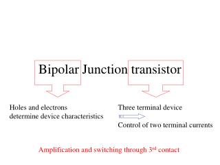
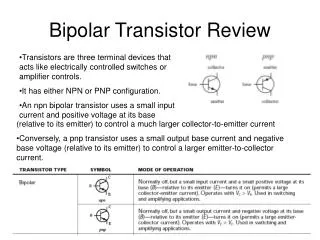
Why are HEMTs smaller & faster than HBTs ? FETs have deep submicron dimensions. 0.1 µm HEMTs with 400 GHz bandwidths (satellites). 5 million 1/4-µm MOSFETs on a 200 MHz, $500 CPU. FET lateral scaling decreases transit times. FET bandwidths then increase. HBTs have ~1 µm junctions. vertical scaling decreases electron transit times. vertical scaling increases RC charging times. lateral scaling should decrease RC charging times. HBT & RTD bandwidths should then increase. But, HBTs must first be modified . . .
Current-gain cutoff frequency in HBTs Collector velocities can be high: velocity overshoot in InGaAsBase bandgap grading reduces transit time substantiallyRC terms quite important for > 200 GHz ft devices
Excess Collector-Base Capacitance in Mesa HBTs • base contacts: must be > 1 transfer length (0.3 mm)® sets minimum collector width® sets minimum collector capacitance Ccb • base resistance spreading resistance scales with emitter scaling contact resistance independent of emitter scaling® sets minimum base resistance® sets minimum RbbCcb time constant • fmax does not improve with submicron scaling
Transferred-Substrate HBTs: A Scalable HBT Technology • Collector capacitance reduces with scaling: • Bandwidth increases rapidly with scaling:
Thinning base, collector epitaxial layers improves ft, degrades fmax Lateral scaling provides moderate improvements in fmax Regrowth (similar to Si BJT !) should help considerably Transferred-substrate helps dramatically
0 . 5 0 - 0 . 5 - 1 - 1 . 5 - 2 0 1 0 0 0 2 0 0 0 3 0 0 0 4 0 0 0 5 0 0 0 6 0 0 0 D i s t a n c e , Å AlInAs/GaInAs graded base HBT C o l l e c t o r d e p l e t i o n r e g i o n E m i t t e r S c h o t t k y c o l l e c t o r G r a d e d b a s e Band diagram under normal operating voltages V = 0.9 V , V = 0.7 V ce be D • 400 Å 5E19 graded base ( E = 2kT), 3000 Å collector g
Transferred-Substrate Heterojunction Bipolar Transistor Device with 0.6 µm emitter & 1.8 µm collector extrapolated fmax at instrument limits, >400 GHz (?) 0.25 µm devices should obtain >1000 GHz fmax
Submicron Transferred-Substrate HBT 0.4 mm x 6 mm emitter, 0.4 mm x 10 mm collector
Emitter Profile: Stepper Device 0.5 mm emitter stripe 0.15 mm e/b junction
Transferred-Substrate HBT: Stepper Lithography 0.4 mm emitter, ~0.7 mm collector
We=0.2 X 6 mm2 Wc=1.5 X 9 mm2 b=50 DC characteristics, stepper device
Given high fmax, vertical scaling exhanges reduced fmax for increased ft
Transit times: HBT with 2kT base grading 2000 Å InGaAs collector400 Å InGaAs base, 2kT bandgap grading
Why would you want a 1 THz transistor ? Digital microwave / RF transmitters (DC-20 GHz) direct digital synthesis at microwave bandwidths microwave digital-analog converters Digital microwave / RF receivers delta-sigma ADCs with 10-30 GHz sample rates 16 effective bits at 100 MHz signal bandwidth ? Basic Science: 0.1 µm Ebeam device: 1000 GHz transistor (?) transistor electronics in the far-infrared Fast fiber optics, fast digital communications: 200 GHz ft, 500 GHz fmax device: ~ 75-90 Gb/s 160 Gb/s needs ~350 GHz ft, 500 GHz fmax
Transferred-Substrate HBT ICs: Key Features 100 GHz clock-rate ICs will need: very fast transistors short wires –> high IC density –> high thermal conductivity low capacitance wiring low ground inductance –> microstrip wiring environment Transferred Substrate HBT ICs offer: 800 GHz fmax now , > 1000 GHz with further scaling250 GHz ft now, >300 GHz with improved emitter Ohmics copper substrates / thermal vias for heatsinking low capacitance (= 2.5) wiring
THz-Bandwidth HBTs ??? deep submicron transferred-substrate regrown-base HBT 2 4 1 5 3 1) regrown P+++ InGaAs extrinsic base --> ultra-low-resistance 2) 0.05 µm wide emitter --> ultra low base spreading resistance 3) 0.05 µm wide collector --> ultra low collector capacitance 4) 100 Å, carbon-doped graded base --> 0.05 ps transit time 5) 1kÅ thick InP collector --> 0.1 ps transit time. Projected Performance: Transistor with 500 GHz ft, 1500 GHz fmax
Why is Improved Wiring Essential? Wire bond creates ground bounce between IC & package ground return loops create inductance 30 GHz M/S D-FF in UCSB - mesa HBT technology Ground loops & wire bonds: degrade circuit & packaged IC performance
digital ADC sections input buffer L ground ground return ground currents D V bounce in noise Ground Bound Noise in ADCs Ground bounce noise must be ~100 dB below full-scale input Differential input will partly suppress ground noise coupling ~ 30 to 40 dB common-mode rejection feasible CMRR insufficient to obtain 100 dB SNR Eliminate ground bounce noise by good IC grounding
Microstrip IC wiring to Eliminate Ground Bounce Noise Transferred-substrate HBT process provides vias & ground plane.
Power Density in 100 GHz logic Transistors tightly packed to minimize delays 105 W/cm2 HBT junction power density. ~103 W/cm2 power density on-chip ® 75 C temperature rise in 500 mm substrate. Solutions: Thin substrate to < 100 mm Replace semiconductor with metal® copper substrate
Transferred-Substrate HBT Integrated Circuits 11 dB, 50+ GHz AGC / limiting amplifier 47 GHz master-slave flip-flop 10 dB, 50+ GHz feedback amplifier 7 dB, 5-80 GHz distributed amplifier
Transferred-Substrate HBT Integrated Circuits multiplexer 16 dB, DC-60 GHz amplifier W-band VCO 2:1 demultiplexer (120 HBTs) 6.7 dB, DC-85 GHz amplifier Clock recovery PLL
Darlington Amplifier - 360 GHz GBW • 15.6 dB DC gain • Interpolated 3dB bandwidth of 60 GHz • 360 GHz gain-bandwidth product
6.7 dB, 85 GHz Mirror Darlington Amplifier • 6.7 dB DC gain • 3 dB bandwidth of 85 GHz • ft-doubler (mirror Darlington) configuration
Master-Slave Flip-Flops CML: 47 GHz ECL: 48 GHz
66 GHz Static Frequency Divider in Transferred-substrate HBT Technology Q. Lee, D. Mensa, J. Guthrie, S. Jaganathan, T. Mathew, Y. Betser, S. Krishnan, S. Ceran, M.J.W. RodwellUniversity of California, Santa Barbara IEEE RFIC’99, Anaheim, California
Fiber Optic ICs (not yet working !) PIN / transimpedance amplifier CML decision circuit AGC / limiting amplifier
Transferred Substrate HBTs • An ultrafast bipolar integrated circuit technology • Ultrahigh fmax HBTs • Low capacitance interconnects • Superior heat sinking, low parasitic packaging • Demonstrated: • HBTs with fmax > 800 GHz • fast flip-flops, 85 GHz amplifiers, ... • Future: • 0.1 mm HBTs with fmax > 1000 GHz • 100 GHz digital logic ICs --> DACs, DDS, ADCs, fiber