PCD End Mill-CBN insert with chip breaker
250 likes | 281 Views
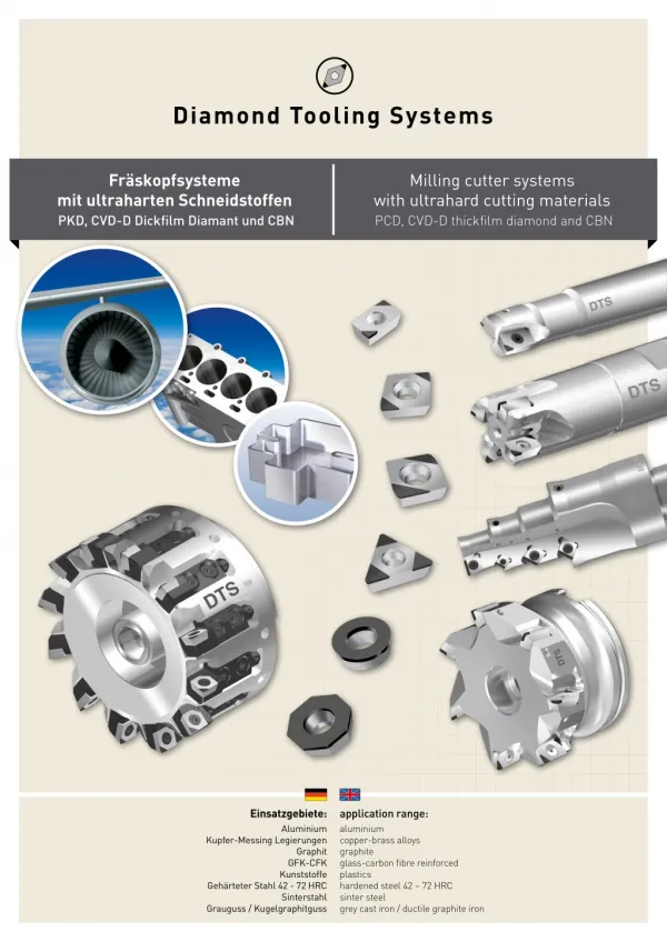
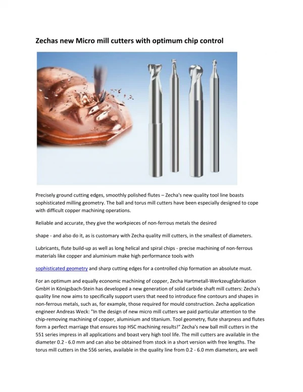
Looking for high-performance PCD End Mill which can machine Nonferrous Metals like Aluminum alloys or Brass and bronze alloys without any micro-damage? If so, Diamond Tooling System is your one-stop solution! Get highest quality PCD End Mill tools at competitive price at DTS!

PCD End Mill-CBN insert with chip breaker
E N D
Presentation Transcript
Fräskopfsysteme mit ultraharten Schneidstoffen PKD, CVD-D Dickfilm Diamant und CBN Milling cutter systems with ultrahard cutting materials PCD, CVD-D thickfilm diamond and CBN Einsatzgebiete: Aluminium application range: aluminium copper-brass alloys graphite glass-carbon fibre reinforced plastics hardened steel 42 – 72 HRC sinter steel grey cast iron / ductile graphite iron Kupfer-Messing Legierungen Graphit GFK-CFK Kunststoffe Gehärteter Stahl 42 - 72 HRC Sinterstahl Grauguss / Kugelgraphitguss
DE | ENG Diamond Tooling Systems GmbH DE | ENG Inhalt | content Located in Kaiserslautern, Germany we are specialized in the development, production and sales of precision tools made from ultra-hard cutting materials such as CVD-D (CVD, thick film di- amond), PCD (polycrystalline diamond) and CBN (cubic boron nitride). We have successfully established these in national and international markets. Mit Sitz in Kaiserslautern-Deutschland haben wir uns auf die Entwicklung, Herstellung und den Vertrieb von Präzisionswerk- zeugen aus ultraharten Schneidstoffen wie CVD-D (CVD-Dickfilm Diamant), PKD (Polykristalliner Diamant) und CBN (Kubisches Bornitrid) spezialisiert und national so wie international erfolg- reich am Markt etabliert. Schneidstoffgruppen groups of cuttingmaterial ������������������������������������4 Weldon-Spannfutter SK weldon-chucks SK ����������������������������������������������23 Formeln formulas ���������������������������������������������������������������5 Weldon-Spannfutter HSK-A weldon-chucks HSK-A ���������������������������������������23 ISO Nummernschlüssel ISO codes ��������������������������������������������������������������6 Plan- / 90° Eck-Aufsteckfräser face and 90° corner end mill �����������������������������24 In order to economically process these ultra-hard cutting materi- als such as PCD, CBN and CVD thick film diamond onto precision tools we noticed at an early stage that we should move on from the older manufacturing technologies such as grinding and advance to newer technologies such as laser technology. Um diese ultraharten Schneidstoffe wie PKD, CVD-D und CBN auf Präzisionwerkzeugen wirtschaftlich bearbeiten zu können haben wir schon früh erkannt, dass wir uns von der alten Produktionstechnologie „Schleifen“ hin zu neuen Technologien wie der „Lasertechnologie“ weiterentwickeln müssen. Senkfräser und Ausbohrer spot facing and boring mill cutters ���������������������8 Schnittdaten Empfehlungen recommended cutting parameters �������������������25 ISO Schneidplatten ISO inserts ������������������������������������������������������������9 Plan- / 90° Eck-Aufsteckfräser face and 90° corner end mill �����������������������������26 Ultra-hard high-performance cutting materials now have a key function and place in the metal cutting industry and production. Precision tools from ultra-hard cutting materials are products which require a more depth of explanation. The economical usage of these materials provides a guarantee when the cutting process and cutting materials are fully aligned. This is where “Diamond Tooling Systems GmbH” comes into the picture. We provide these precision tools made from such ultra-hard cutting materials. Ultraharte Hochleistungsschneidstoffe haben eine Schlüssel- funktion in der spanenden Fertigung. Präzisionswerkzeuge aus ultraharten Schneidstoffen sind sehr erklärungsbedürftige Produkte. Der wirtschaftliche Einsatz der Schneidstoffe ist nur sichergestellt, wenn der Zerspanungspro- zess und der Schneidstoff aufeinander abgestimmt sind. Einstellbare Feinbohrstangen adjustement boring bars ������������������������������������10 ISO Schneidplatten milling ISO inserts ����������������������������������������������27 ISO Schneidplatten ISO inserts ����������������������������������������������������������11 Einstellbare Kassettenfräser mit IK adjustable milling cutter with IC ����������������28 – 29 Eckfräser shoulder milling cutter ��������������������������������������12 Einstellbare Kassettenfräser mit IK adjustable milling cutter with IC �����������������������30 Genau hier setzt Diamond Tooling Systems GmbH an, „Unse- re Kernkompetenz sind Präzisionswerkzeuge aus ultrahar- ten Schneidstoffen“. Diese Hightech-Werkzeuge müssen zum Zerspanungsprozess mit Anwendungstechnikern genau abge- stimmt werden, nur so ist es möglich, das optimale Potenzial auszuschöpfen. ISO Schneidplatten milling ISO inserts ����������������������������������������������13 Wechselkassette adjustable cartridge �������������������������������������������31 These high-tech tools require together with an experienced appli- cation engineer a need to be aligned with the cutting process in order to exploit their optimal potential. Our strengths lie in having more than 25 years of optimization experience within the produ- cing industry. During the initial stages of running production, we will be by your side offering a professional consultation service along with our experienced application engineers. This side by side cooperation based on mutual trust is the keystone of our success. Einschraub- /Gesenkfräser threaded type milling cutter ������������������������������14 ISO Schneidplatten milling ISO inserts ���������������������������������������32 – 33 VHM Verlängerungen carbide adapters ������������������������������������������������14 Einstellanleitung adjusting guidelines �������������������������������������������34 Mit mehr als 25 Jahren Optimierungserfahrung in der verar- beitenden Industrie sehen wir hier unsere Stärke! Während der laufenden Produktion stehen wir Ihnen mit unseren erfahrenen Anwendungstechnikern beratend zur Seite. Diese enge Zusam- menarbeit und das gegenseitige Vertrauen ist die Basis unseres Erfolges. ISO Schneidplatten milling ISO inserts ����������������������������������������������15 Breitschlicht Wendeplatten finish insert ���������������������������������������������������������35 Plan- / 90°-Eck-Weldonschaftfräser face and 90° corner weldon end mill �����������������16 Koblenz Messerkopfaufnahmen milling cutter interfaces ������������������������������������36 Frankfurt am Main Wiesbaden Schnittdaten Empfehlungen recommended cutting parameters �������������������17 SK Steilkegel Messerkopfaufnahmen steep taper SK ����������������������������������������������������37 Mainz Plan- / 90°-Eck-Weldonschaftfräser face and 90° corner weldon end mill �����������������18 HSK Messerkopfaufnahmen HSK interfaces����������������������������������������������������38 ISO Schneidplatten milling ISO inserts ����������������������������������������������19 BT Messerkopfaufnahmen BT interfaces ������������������������������������������������������39 Kaiserslautern Mannheim Kaiserslautern Weldon-Hydrodehnspannfutter hydraulic-sidelock chucks ���������������������������������20 Kombiwerkzeuge mit PKD- CVD- und CBN- ISO Schneidplatten combination tools with PCD- /CVD- and CBN- ISO inserts �����40 – 41 Saarbrücken Einstellanleitung adjusting guidelines �������������������������������������������21 Karlsruhe Checkliste checklist �������������������������������������������������������42 / 43 Weldon-Hydrodehnspannfutter SK hydraulic-sidelock chucks SK ���������������������������22 Stuttgart Zubehör spare parts ��������������������������������������������������44 – 46 Weldon-Hydrodehnspannfutter HSK-A hydraulic-sidelock chucks HSK-A ���������������������22 2 2 3 3
DE | ENG Schneidstoffgruppen | groups of cuttingmaterial DE | ENG Formeln | formulas metrisch | metric Zoll | inch Härte | hardness (kg/mm²) min. Binder 10.000 Formel | formula Einheiten | units Formel | formula Einheiten | units CVD 9.000 Zoll / min inch / min Vorschubgeschwindigkeit feed rate mm / min Vf = fn x n Vf = fn x n 8.000 Spindeldrehzahl spindle speed U / min rev / min U / min rev / min Vc x 12 π x DCap n = Vc x 1000 π x DCap 7.000 n = CVD-Thickfilm Diamond 6.000 PKD Vorschub pro Umdrehung feed per revolution mm / U mm / rev Zoll / U inch / rev Vf n Vf n PCD fn = fn = 5.000 Bearbeitungszeit cutting time lm lm 4.000 T c = T c = min min fn x n fn x n CBN 3.000 Zeitspanvolumen stock removal rate Zoll3 / min inch3 / min cm3 / min Q = V c x ap x fn Q = V c x ap x fn x 12 2.000 1.000 0 MKD MCD Naturdiamant natural diamond PKD PCD CBN CBN Keramik ceramic Hartmetall carbide Stahl steel CVD Dickfilm Diamant – der härteste Schneidstoff der Welt! CVD Thickfilm Diamond the hardest cutting material of the world! Der ultraharte Schneidstoff „CVD-Dickfilm Diamant“ besitzt die höchste Härte und den höchsten Verschleiß- widerstand aller untersuchten Schneidstoffe. The mostly used “PCD cutting material” has in comparison to the “CVD-thickfilm diamond” clear drawbacks due to its soft metallic binder. In several tests it has been proven that especially the soft binder of the PCD is damaged through abrasive particles. Der „PKD Schneidstoff“ hat im Gegensatz zum „CVD-Dickfilm Diamant“ deutliche Nachteile aufgrund seiner weichen metallischen Bindephase. In zahlrei- chen Versuchen konnte nachgewiesen werden, dass vor allem die weiche Bindephase des PKD durch die abrasi- ven Partikel geschädigt wird. Die Folge ist ein Ausbre- chen der Diamantkristalle aufgrund einer verminderten Verankerung in der Schneidstoffmatrix. The consequence is a break out of the diamond crystals due to a reduced anchorage in the cutting material matrix. The consequence of this is that by the machining of alumi- num – and magnesium alloys and also non ferrous mate- rials preferably diamond is used as cutting material. The clean diamond segments, which in most cases are brazed onto a carbide insert. Bei richtigem Einsatz von CVD-Dickfilm Diamant kön- nen die Standzeiten gegenüber PKD um das 3-10fache erhöht werden! The tool life can be increased with CVD thickfilm diamond approx 3 to 10 times vs. PCD. 4 4 5 5
DE | ENG ISO Nummernschlüssel | ISO codes Notizen | Notes T N A 16 04 08 G Grundform | shape C D O R S T V W 35° 90° 80° 55° 80° 135° 60° A B E H K L M P 85° 82° 55° 90° 75° 86° 120° 108° N T A 16 04 08 G Freiwinkel | clearance A B C D E F G N P 0° 11° 5° 20° 25° 3° 15° 30° 7° G T N A 16 04 08 Toleranz (mm) | tolerance (mm) m s d m s d m s ± 0,005 ± 0,025 ± 0,025 ± 0,005 ± 0,025 ± 0,05 → ± 0,15 A d m ± 0,005 ± 0,025 ± 0,013 ± 0,013 ± 0,025 ± 0,05 → ± 0,15 m ± 0,013 ± 0,025 ± 0,025 ± 0,025 ± 0,025 ± 0,05 → ± 0,15 d d ± 0,013 ± 0,025 ± 0,013 ± 0,08 → ± 0,20 ± 0,130 ± 0,05 → ± 0,15 m m ± 0,025 ± 0,025 ± 0,025 ± 0,08 → ± 0,20 ± 0,25 ± 0,05 → ± 0,15 ± 0,025 ± 0,130 ± 0,025 ± 0,13 → ± 0,38 ± 0,130 ± 0,08 → ± 0,15 d d *(M, N, U) Die genaue Toleranz ist von der Größe der Platte abhängig | Die genaue Toleranz ist von der Größe der Platte abhängig A N 16 04 08 T G Plattentyp | insert type N W F R X A T G M Spezialausführung Special Type A 16 04 T N 08 G Plattengröße (mm) | insert size (mm) C O R S D E H P L A B K W T M V l l l d l l l l l l 16 04 08 T N A G Dicke (mm) | insert size (mm) s = 1,59 s = 1,98 s = 2,38 s = 3,18 s = 3,97 s = 4,76 s = 5,56 s = 6,35 01 T1 02 03 T3 04 05 06 s Bei Ziffern unter 10 wird eine Null vorgesetzt. Dezimalstellen bleiben unberücksichtigt. (Beispiel: 4,76 = 04) By numbers below 10 a 0 is added in at the front. Decimals remain unconsidered (example: 4,76 = 04) 04 08 N A 16 T G Schneidenecke (mm) | corner configuration (mm) scharfe Ecke sharp corner runde Platte (metrisch) round insert (metric) runde Platte (inch) round insert (inch) 00 00 M0 r r = 0,2 r = 0,4 r = 0,8 r = 12 r = 16 02 04 08 12 16 6 6 7 7
Senkfräser und Ausbohrer | Spot facing and boring milling cutters ISO Schneidplatten | ISO inserts d d2 F min Ø l2 l r l1 Z1 für Schneidplatten for inserts d d2 F min Ø l l2 z DTS Code 10,00 12 h6 4,00 85,00 15,00 1 CCGW 0602 L-GS FW7060-0310 PKD CVD CBN CBN 11,00 12 h6 4,00 85,00 15,00 1 CCGW 0602 L-GS FW7060-0311 PCD 12,00 12 h6 4,00 85,00 18,00 1 CCGW 0602 L-GS FW7060-0312 ISO Wendeschneidplatten | ISO inserts 13,00 12 h6 5,00 85,00 23,00 1 CCGW 0602 L-GS FW7060-0313 Für Ø d for Ø d 14,00 12 h6 5,00 85,00 23,00 1 CCGW 0602 L-GS FW7060-0314 ISO Code l1 DTS Code DTS Code DTS Code DTS Code 15,00 12 h6 5,00 85,00 30,00 1 CCGW 0602 L-GS FW7060-0315 CCGW 060202 L-GS 10,00 – 24,00 6,00 DP1029-0064 DP2029-0064 TI5020-0010 TI5520-0010 CCGW 060204 L-GS 10,00 – 24,00 6,00 DP1029-0050 DP2029-0050 TI5020-0015 TI5520-0015 F min Ø d d2 l2 CCGW 060208 L-GS 10,00 – 24,00 6,00 DP1029-0051 DP2029-0051 TI5020-0020 TI5520-0020 l für Schneidplatten for inserts CCGW 09T302 L-GS 25,00 – 32,00 9,00 DP1029-0062 DP2029-0062 TI5020-0050 TI5520-0050 d d2 F min Ø l l2 z DTS Code 15,00 12 h6 5,00 92,00 30,00 2 CCGW 0602 L-GS FW7060-0415 CCGW 09T304 L-GS 25,00 – 32,00 9,00 DP1029-0065 DP2029-0065 TI5020-0055 TI5520-0055 16,00 12 h6 5,00 92,00 30,00 2 CCGW 0602 L-GS FW7060-0416 17,00 16 h6 6,00 94,00 32,00 2 CCGW 0602 L-GS FW7060-0417 CCGW 09T308 L-GS 25,00 – 32,00 9,00 DP1029-0052 DP2029-0052 TI5020-0060 TI5520-0060 17,50 16 h6 6,50 96,00 40,00 2 CCGW 0602 L-GS FW7060-1417 18,00 16 h6 7,00 97,00 41,00 2 CCGW 0602 L-GS FW7060-0418 19,00 16 h6 8,00 100,00 41,00 2 CCGW 0602 L-GS FW7060-0419 20,00 16 h6 9,00 102,00 41,00 2 CCGW 0602 L-GS FW7060-0420 21,00 16 h6 10,00 105,00 41,00 2 CCGW 0602 L-GS FW7060-0421 22,00 16 h6 11,00 110,00 41,00 2 CCGW 0602 L-GS FW7060-0422 23,00 16 h6 12,00 112,00 41,00 2 CCGW 0602 L-GS FW7060-0423 24,00 16 h6 13,00 115,00 41,00 2 CCGW 0602 L-GS FW7060-0424 25,00 16 h6 8,00 120,00 40,00 2 CCGW 09T3 L-GS FW7060-0425 26,00 20 h6 9,00 125,00 55,00 2 CCGW 09T3 L-GS FW7060-0426 27,00 20 h6 10,00 128,00 55,00 2 CCGW 09T3 L-GS FW7060-0427 28,00 20 h6 11,00 130,00 55,00 2 CCGW 09T3 L-GS FW7060-0428 29,00 20 h6 12,00 132,00 55,00 2 CCGW 09T3 L-GS FW7060-0429 30,00 20 h6 13,00 134,00 55,00 2 CCGW 09T3 L-GS FW7060-0430 31,00 20 h6 14,00 136,00 55,00 2 CCGW 09T3 L-GS FW7060-0431 Aluminium Knetlegierungen Aluminium alloys Si 1% - 38% (CVD), Si 1% - 12% (PCD) Gehärteter Stahl Hardened Steel 42-72 HRC Einsatzstahl, Vergütungsstahl, Werkzeugstahl, Kugelstahl Case Hardened Steel, Heat Treated Steel Grauguss Grey Cast Iron GG20, GG25, GG30 Gusseisen mit Kugelgraphit Ductile Graphite Iron GGG40, GGG50, GGG60 32,00 20 h6 15,00 138,00 55,00 2 CCGW 09T3 L-GS FW7060-0432 Kupfer Messing Legierungen, Graphit, GFK-CFK, Zirkon Copper Brass alloys, Graphite, Glass-Carbone fibre reinforced, Zirconium (CVD) Ersatzschrauben für WSP siehe Seite 44 spare screws for inserts see page 44 Technische Änderungen vorbehalten | Technical data subject to change without prior notice Technische Änderungen vorbehalten | Technical data subject to change without prior notice 8 9
Einstellbare Feinbohrstangen | Adjustement boring bars ISO Schneidplatten | ISO inserts Dmin - Dmax d2 l2 l r l1 Z1 Bearbeitung erfolgt ohne Kühlung machining without coolant Dmin Dmax d2 l l2 z DTS Code PKD CVD CBN CBN PCD 10,00 12,00 10 h6 100,00 30,00 1 BW7060-0910 ISO Wendeschneidplatten | ISO inserts Für Ø d for Ø d ISO Code l1 DTS Code DTS Code DTS Code DTS Code 12,00 15,00 12 h6 105,00 30,00 1 BW7060-0912 15,00 20,00 16 h6 110,00 50,00 1 BW7060-0915 CCGW 060202 10,00 – 20,00 3,00 DP1010-0021 DP2010-0021 TI5010-8010 TI5510-8010 20,00 25,00 20 h6 120,00 60,00 1 BW7060-0920 CCGW 060204 10,00 – 20,00 3,00 DP1010-0022 DP2010-0022 TI5010-8015 TI5510-8015 25,00 30,00 25 h6 140,00 70,00 1 BW7060-0925 CCGW 060208 10,00 – 20,00 3,00 DP1010-0023 DP2010-0023 TI5010-8020 TI5510-8020 30,00 35,00 25 h6 160,00 30,00 1 BW7060-0930 CCGW 09T302 25,00 – 30,00 3,00 DP1010-0024 DP2010-0024 TI5010-8025 TI5510-8025 Ersatzschrauben für WSP siehe Seite 46 spare screws for inserts see page 46 CCGW 09T304 25,00 – 30,00 3,00 DP1010-0025 DP2010-0025 TI5010-8030 TI5510-8030 CCGW 09T308 25,00 – 30,00 3,00 DP1010-0026 DP2010-0026 TI5010-8035 TI5510-8035 Einen Überblick über das gesamte Sortiment finden sie in unseren PKD/CVD- und CBN- Schneidplatten-Katalogen An overview of the entire product range can be found in our PCD/CVD and CBN insert catalogues Aluminium Knetlegierungen Aluminium alloys Si 1% - 38% (CVD), Si 1% - 12% (PCD) Gehärteter Stahl Hardened Steel 42-72 HRC Einsatzstahl, Vergütungsstahl, Werkzeugstahl, Kugelstahl Case Hardened Steel, Heat Treated Steel Grauguss Grey Cast Iron GG20, GG25, GG30 Gusseisen mit Kugelgraphit Ductile Graphite Iron GGG40, GGG50, GGG60 Kupfer Messing Legierungen, Graphit, GFK-CFK, Zirkon Copper Brass alloys, Graphite, Glass-Carbone fibre reinforced, Zirconium (CVD) Technische Änderungen vorbehalten | Technical data subject to change without prior notice Technische Änderungen vorbehalten | Technical data subject to change without prior notice 10 11
Eckfräser | Shoulder milling cutters ISO Schneidplatten | Milling ISO inserts d2 d l2 l r l1 Z2 für Schneidplatten for inserts d d2 l l2 z DTS Code PKD CVD CBN CBN PCD 10,00 10 h6 100,00 28,00 2 AOEX 0402.. FW7060-0050 ISO Wendeschneidplatten | ISO inserts Eck-Ausführung face cutting ISO Code l1 DTS Code DTS Code DTS Code DTS Code 12,00 12 h6 100,00 30,00 3 AOEX 0402.. FW7060-0055 14,00 12 h6 120,00 32,00 3 AOEX 0402.. FW7060-0060 AOEX 040202 2,00 MI1010-0020 MI2010-0020 MI5010-0020 MI5510-0020 Ersatzschrauben für WSP siehe Seite 44 spare screws for inserts see page 44 AOEX 040204 2,00 MI1010-0025 MI2010-0025 MI5010-0025 MI5510-0025 Z2 AOEX 040208 2,00 MI1010-0030 MI2010-0030 MI5010-0030 MI5510-0030 Aluminium Knetlegierungen Aluminium alloys Si 1% - 38% (CVD), Si 1% - 12% (PCD) Gehärteter Stahl Hardened Steel 42-72 HRC Einsatzstahl, Vergütungsstahl, Werkzeugstahl, Kugelstahl Case Hardened Steel, Heat Treated Steel Grauguss Grey Cast Iron GG20, GG25, GG30 Gusseisen mit Kugelgraphit Ductile Graphite Iron GGG40, GGG50, GGG60 Kupfer Messing Legierungen, Graphit, GFK-CFK, Zirkon Copper Brass alloys, Graphite, Glass-Carbone fibre reinforced, Zirconium (CVD) Technische Änderungen vorbehalten | Technical data subject to change without prior notice Technische Änderungen vorbehalten | Technical data subject to change without prior notice 12 13
Einschraub-/Gesenkfräser | Threaded type milling cutter ISO Schneidplatten | Milling ISO inserts d2 d M r l1 Z2 l für Schneidplatten for inserts d d2 l M z DTS Code PKD CVD CBN CBN PCD 10,00 6,50 16,00 M6 2 AOEX 0402.. FW7060-0510 ISO Wendeschneidplatten | ISO inserts Eck-Ausführung face cutting ISO Code l1 DTS Code DTS Code DTS Code DTS Code 12,00 6,50 16,00 M6 3 AOEX 0402.. FW7060-0512 AOEX 040202 2,00 MI1010-0020 MI2010-0020 MI5010-0020 MI5510-0020 VHM Verlängerungen | Carbide adapters AOEX 040204 2,00 MI1010-0025 MI2010-0025 MI5010-0025 MI5510-0025 Z2 AOEX 040208 2,00 MI1010-0030 MI2010-0030 MI5010-0030 MI5510-0030 SV d2 d l2 l LV d2 d l2 l d2 d l l2 M Version DTS Code 10h6 9,80 150,00 30,00 6 LV FW6065-0200 12h6 10,80 150,00 27,00 6 LV FW6065-0205 12h6 9,70 60,00 30,00 6 SV FW6065-0100 9,70 80,00 50,00 6 SV FW6065-0105 9,70 100,00 60,00 6 SV FW6065-0110 9,70 150,00 70,00 6 SV FW6065-0115 Ersatzschrauben für WSP siehe Seite 44 spare screws for inserts see page 44 Aluminium Knetlegierungen Aluminium alloys Si 1% - 38% (CVD), Si 1% - 12% (PCD) Gehärteter Stahl Hardened Steel 42-72 HRC Einsatzstahl, Vergütungsstahl, Werkzeugstahl, Kugelstahl Case Hardened Steel, Heat Treated Steel Grauguss Grey Cast Iron GG20, GG25, GG30 Gusseisen mit Kugelgraphit Ductile Graphite Iron GGG40, GGG50, GGG60 Kupfer Messing Legierungen, Graphit, GFK-CFK, Zirkon Copper Brass alloys, Graphite, Glass-Carbone fibre reinforced, Zirconium (CVD) Technische Änderungen vorbehalten | Technical data subject to change without prior notice Technische Änderungen vorbehalten | Technical data subject to change without prior notice 14 15
Plan- / 90°-Eck-Weldonschaftfräser | Face and 90° corner weldon end mill Schnittdaten Empfehlungen | recommended cutting parameters Weldon-Schaftfräser Ø16mm bis Ø25mm für ultraharte Schneidstoffe Weldon end mill Ø16mm up to Ø25mm for ultrahard cutting edges Schnittwerte für PKD - CVD-D - CBN | Cutting parameters for PCD - CVD-D - CBN Nichteisenhaltige Werkstoffe | Non Ferrous Materials Vc - max. ap - 0,10 Vc - max. ap - 1,5mm Vc - max. ap - 2,80mm Vc - max. ap - 7,0mm fz max. mm/z Vorteile: • Gute Rundlaufgenauigkeit • Schneller Einsatz • Hohe Schnittwerte möglich • Sehr wirtschaftlich durch Mehrfachbestückung Advantages: • Good concentricity • Fast installation • High cutting speed possible • Very economic Werkstoff | material PKD CVD PKD CVD PKD CVD PKD CVD Aluminium Legierungen AluminiumAlloys < Si 1 % Aluminium Legierungen AluminiumAlloys < Si 12 % Aluminium Legierungen AluminiumAlloys > Si 13 % 4500 5000 4500 5000 4000 4500 3500 4000 0,40 4000 4500 4000 4500 3500 4000 3000 3000 0,35 3000 3500 2500 3000 2000 2500 1000 1500 0,30 Magnesium Legierungen Magnesium Alloys 4500 5000 4500 5000 4000 4500 3500 4000 0,40 Kupfer Legierungen Copper Alloys 4000 4500 3500 4000 3000 3500 1500 2000 0,25 Messing Legierungen Brass Alloys 3000 4500 2500 3000 2000 2500 1000 1500 0,30 Graphit | Graphite 3500 4000 3000 3500 2500 2000 1500 2000 0,30 GFK | Glass fibre reinforced 3000 3500 2500 3000 2000 2500 1000 1500 0,40 CFK | Carbon fibre reinforced 3000 3500 2500 3000 2000 2500 800 1200 0,40 Schnittwerte für CBN | Cutting parameters for CBN Eisenhaltige Werkstoffe | Ferrous Materials Vc - max. ap - 0,10 Vc - max. ap - 1,5mm Vc - max. ap - 2,80mm Vc - max. ap - 9,0mm fz max. mm/z Werkstoff | material CBN CBN CBN CBN CBN CBN CBN CBN Alle Planfräs-Wendeplatten mit zwei Schneiden All face milling inserts tipped with two cutting edges Stahl gehärtet bis 72HRC Hardened steel up to 72 HRC 300 250 0,30 Werkzeugstahl gehärtet bis 72 HRC Tool steel up to 72 HRC CL 3,0 / Z2 200 200 200 200 0,25 Pulverstahl wie ASP gehärtet Powder steel, ASP 200 200 200 200 0,25 Alle Eckfräs-Wendeplatten mit zwei Schneiden All corner milling inserts tipped with two cutting edges Guss | Cast iron 2000 2000 1500 1200 0,40 CL 7,0 / Z2 Aluminium Knetlegierungen Aluminium alloys Si 1% - 38% (CVD), Si 1% - 12% (PCD) Gehärteter Stahl Hardened Steel 42-72 HRC Einsatzstahl, Vergütungsstahl, Werkzeugstahl, Kugelstahl Case Hardened Steel, Heat Treated Steel Grauguss Grey Cast Iron GG20, GG25, GG30 Gusseisen mit Kugelgraphit Ductile Graphite Iron GGG40, GGG50, GGG60 Kupfer Messing Legierungen, Graphit, GFK-CFK, Zirkon Copper Brass alloys, Graphite, Glass-Carbone fibre reinforced, Zirconium (CVD) Technische Änderungen vorbehalten | Technical data subject to change without prior notice Technische Änderungen vorbehalten | Technical data subject to change without prior notice 16 17
Plan- / 90°-Eck-Weldonschaftfräser | Face and 90° corner weldon end mill ISO Schneidplatten | Milling ISO inserts Zylinderschaft mit Weldonfläche Cylindric shaft with weldon Mit IK | with inner coolant Plattenwinkel axial 5° Insert angle axial 5° 90° bis 7mm 90° up to 7mm d2 d l2 r l1 l Z2 d d2 l l2 z n max DTS Code PKD CVD CBN CBN PCD 16,00 16 h6 80,00 30,00 2 32.000 FW7060-0100 ISO Wendeschneidplatten | ISO inserts Plan-Ausführung face cutting 16 h6 90,00 40,00 2 32.000 FW7060-0105 ISO Code l1 DTS Code DTS Code DTS Code DTS Code 20,00 20 h6 95,00 40,00 3 28.000 FW7060-0110 AOEX 07T302 3,00 MI1010-0050 MI2010-0050 MI5010-0050 MI5510-0050 20 h6 105,00 50,00 3 28.000 FW7060-0115 AOEX 07T304 3,00 MI1010-0055 MI2010-0055 MI5010-0055 MI5510-0055 Z2 25,00 25 h6 110,00 50,00 3 24.000 FW7060-0120 AOEX 07T308 3,00 MI1010-0060 MI2010-0060 MI5010-0060 MI5510-0060 25 h6 135,00 75,00 3 24.000 FW7060-0125 AOEX 07T312 3,00 MI1010-0064 MI2010-0064 MI5010-0064 MI5510-0064 25 h6 110,00 50,00 4 24.000 FW7060-0130 AOEX 07T316 3,00 MI1010-0065 MI2010-0065 MI5010-0065 MI5510-0065 25 h6 135,00 75,00 4 24.000 FW7060-0135 Ersatzschrauben für WSP siehe Seite 44 spare screws for inserts see page 44 Eck-Ausführung corner cutting ISO Code l1 DTS Code DTS Code DTS Code DTS Code Fräsbahnen so einteilen, dass der Fräser gleichmäßig belastet wird Use milling cutter equally loaded AOEX 07T302 7,00 MI1025-0050 MI2025-0050 MI5025-0050 MI5525-0050 AOEX 07T304 7,00 MI1025-0055 MI2025-0055 MI5025-0055 MI5525-0055 Z2 AOEX 07T308 7,00 MI1025-0060 MI2025-0060 MI5025-0060 MI5525-0060 AOEX 07T312 7,00 MI1025-0064 MI2025-0064 MI5025-0064 MI5525-0064 AOEX 07T316 7,00 MI1025-0065 MI2025-0065 MI5025-0065 MI5525-0065 Aluminium Knetlegierungen Aluminium alloys Si 1% - 38% (CVD), Si 1% - 12% (PCD) Gehärteter Stahl Hardened Steel 42-72 HRC Einsatzstahl, Vergütungsstahl, Werkzeugstahl, Kugelstahl Case Hardened Steel, Heat Treated Steel Grauguss Grey Cast Iron GG20, GG25, GG30 Gusseisen mit Kugelgraphit Ductile Graphite Iron GGG40, GGG50, GGG60 Kupfer Messing Legierungen, Graphit, GFK-CFK, Zirkon Copper Brass alloys, Graphite, Glass-Carbone fibre reinforced, Zirconium (CVD) Technische Änderungen vorbehalten | Technical data subject to change without prior notice Technische Änderungen vorbehalten | Technical data subject to change without prior notice 18 19
Weldon-Hydrodehnspannfutter | Hydraulic-sidelock chucks Einstellanleitung | Adjusting guidelines Weldonschaft DIN 1835-B Weldon shaft DIN 1835-B Zwei Spannsysteme werden in einem Spannfutter vereint, das Resultat ist eine Hightech-Aufnahme Two clamping systems are combined in a chuck, the result is a hightech clamping system Weldon-Aufnahmen, oder auch Flächenspannfutter für Zylinder- schäfte sind auf Grund ihrer schlichten Ausführung, einfacher Bedienbarkeit und hohen Spannkräften sehr beliebt. Weldon holders or surface clamping chucks for cylindrical shanks are very popular due to their straightforward design, simple ope- ration and high clamping forces. Using the Weldon hydro clamp chuck, you can clamp end mills with great precision and anti-twist protection, whilst achieving excellent vibration damping as well. This ensures the necessary concentricity of the ultra-hard cutting materials. Mit dem Weldon-Hydrodehnspannfutter können Sie Schaftfräser hochgenau, verdrehsicher spannen. Des Weiteren erreichen Sie eine sehr gute Vibrationsdämpfung. Der erforderliche Rundlauf der ultraharten Schneide wird somit sichergestellt. Hier die Vorteile in Übersicht: Winning features – an overview: Weldon Schraube Weldon screw • Hohe Dämpfung gegen Vibrationen • Bester Rundlauf der Werkzeugschneide • Exakte Positionierung der Werkzeugschneide • Sicherung gegen Verdrehen • Einfache Bedienung • Deutlich bessere Oberflächen • Standzeiterhöhung von bis zu 50% • High degree of damping against vibration • Excellent concentricity of the cutting edge • Exact positioning of the cutting edge • Simple to use and secured against twisting • Noticeably better surfaces • Up to 50% increase in tool life 100% radiale-axiale Sicherheit Beste Oberflächen Erhöhte Prozessicherheit Standzeitferhöhung von bis zu 50% Geeignet zur Aufnahme von Zylinderschäften nach DIN 6535 mit Weldon- und Whistle Notch Spannflächen (Form HB und HE). For tools with shanks accordance with DIN 6535 (Weldon and Whistle Notch, HB and HE). 100 % radiale-axiale security Best surfaces Safety process Increase life time up to 50% Notizen | notes Weldon-Schraube leicht anlegen (Orientierung) Spannen des Hydrodehn (max. 10 Nm) Spannen DIN 1835 (max. 15 Nm) Orientation Weldon screw to Weldon flat Turn hydraulik clamping screw (max. 10 Nm) Turn sidelock clamping screw (max. 15 Nm) Technische Änderungen vorbehalten | Technical data subject to change without prior notice 20 20 21
Weldon-Hydrodehnspannfutter - SK | Hydraulic-sidelock chucks - SK Weldon-Spannfutter - SK | Weldon-chucks - SK DIN 69871 Form AD+B SK40 / SK50 DIN 69871 SK-40 / SK-50 l3 Spanntiefe d1 d2 d3 d4 d1 d2 g g m m l5 l2 l1 l1 Aufnahme | Chuck Abmessungen | Dimensions Aufnahme | Chuck Abmessungen | Dimensions Type DTS Code d1 d2 d3 d4 l1 l2 l3 l5 G g M Type DTS Code d1 d2 l1 G g M SK40 SK40 SK40 SK50 SK50 SK50 WA7090-0400 WA7090-0405 WA7090-0410 WA7090-0420 WA7090-0425 WA7090-0430 16,00 20,00 25,00 16,00 20,00 25,00 34,00 38,00 46,00 34,00 38,00 46,00 38,00 42,00 50,00 38,00 42,00 50,00 50,00 50,00 50,00 80,00 80,00 80,00 80,00 82,00 117,0 80,00 82,00 117,0 60,90 62,90 97,90 60,90 62,90 97,90 52,00 52,00 58,00 52,00 52,00 58,00 45,00 47,00 - 45,00 47,00 52,00 SK-40 SK-40 SK-40 SK-50 SK-50 SK-50 WA7090-0500 WA7090-0505 WA7090-0510 WA7090-0520 WA7090-0525 WA7090-0530 16,00 20,00 25,00 16,00 20,00 25,00 48,00 52,00 65,00 48,00 52,00 65,00 63,00 63,00 100,00 63,00 63,00 80,00 M16 M16 M16 M24 M24 M24 M12 x 1 M12 x 1 M16 x 1 M12 x 1 M12 x 1 M16 x 1 M14 M16 M18 x 2 M14 M16 M18 x 2 M16 M12 x 1 M14 M16 M12 x 1 M16 M16 M16 x 1 M18 x 2 M24 M12 x 1 M14 M24 M12 x 1 M16 M24 M16 x 1 M18 x 2 Verwendung: Weldon-Hydrodehnspannfutter für Werkzeugschäfte nach DIN 1835 B+E Application: Hydraulik-Sidelock chucks with DIN 1835-B clamping screw and central coolant supply by means of adjusting screw Verwendung: Weldon-Spannfutter für Werkzeugschäfte nach DIN 1835 B+E Application: Weldon-chucks with DIN 1835-B clamping screw and central coolant supply by means of adjusting screw Weldon-Hydrodehnspannfutter - HSK-A | Hydraulic-sidelock chucks - HSK-A Weldon-Spannfutter - HSK-A | Weldon-chucks - HSK-A DIN 69893 HSK-A63 / HSK-A100 JIS B 69893 HSK-A63 / HSK-A100 l3 Spanntiefe d1 d2 d3 d4 d2 d1 m l5 l2 m l1 l1 Aufnahme | Chuck Abmessungen | Dimensions Aufnahme | Chuck Abmessungen | Dimensions Type DTS Code d1 d2 d3 d4 l1 l2 l3 l5 G g M Type DTS Code d1 d2 l1 G g M HSK-A63 HSK-A63 HSK-A63 HSK-A100 HSK-A100 HSK-A100 WA7090-0440 WA7090-0445 WA7090-0450 WA7090-0460 WA7090-0465 WA7090-0470 16,00 20,00 25,00 16,00 20,00 25,00 34,00 38,00 46,00 34,00 38,00 46,00 38,00 42,00 50,00 38,00 42,00 50,00 50,00 50,00 - 50,00 50,00 63,00 95,00 100,0 120,0 100,0 105,0 115,0 69,00 74,00 94,00 71,00 76,00 86,00 52,00 52,00 58,00 52,00 52,00 58,00 52,00 58,00 - 53,00 59,00 51,00 HSK-A63 HSK-A63 HSK-A63 HSK-A100 HSK-A100 HSK-A100 WA7090-0540 WA7090-0545 WA7090-0550 WA7090-0560 WA7090-0565 WA7090-0570 16,00 20,00 25,00 16,00 20,00 25,00 48,00 52,00 65,00 48,00 52,00 65,00 80,00 80,00 110,00 100,00 100,00 100,00 M12 x 1 M12 x 1 M16 x 1 M12 x 1 M12 x 1 M16 x 1 M14 M16 M18 x 2 M14 M16 M18 x 2 M14 M16 M18 x 2 M14 M16 M18 x 2 M12 x 1 M14 M14 M12 x 1 M16 M16 M16 x 1 M18 x 2 M18 x 2 M12 x 1 M14 M14 M12 x 1 M16 M16 M16 x 1 M18 x 2 M18 x 2 Verwendung: Weldon-Hydrodehnspannfutter für Werkzeugschäfte nach DIN 1835 B+E Application: Hydraulik-Sidelock chucks with DIN 1835-B clamping screw and central coolant supply by means of adjusting screw Verwendung: Weldon-Hydrodehnspannfutter für Werkzeugschäfte nach DIN 1835 B+E Application: Hydraulik-Sidelock chucks with DIN 1835-B clamping screw and central coolant supply by means of adjusting screw Technische Änderungen vorbehalten | Technical data subject to change without prior notice Technische Änderungen vorbehalten | Technical data subject to change without prior notice 22 23
Plan- / 90°-Eck-Aufsteckfräser | Face and 90° corner end mill Schnittdaten Empfehlungen | recommended cutting parameters Aufsteckfräser von Ø32 bis Ø100 für ultraharte Schneiden mit PKD – CVD-D und CBN Milling cutter Ø32 up to Ø100 for ultrahard cuttings with PCD - CVD-D and CBN Schnittwerte für PKD - CVD-D - CBN | Cutting parameters for PCD - CVD-D - CBN Nichteisenhaltige Werkstoffe | Non Ferrous Materials Vc - max. ap - 0,10 Vc - max. ap - 1,5mm Vc - max. ap - 2,80mm Vc - max. ap - 7,0mm fz max. mm/z Werkstoff | material Vorteile: • Gute Rundlaufgenauigkeit • Schneller Einsatz • Hohe Schnittwerte möglich • Sehr wirtschaftlich durch Mehrfachbestückung Advantages: • Good concentricity • Fast Installation • High cutting speed possible • Very economic PKD CVD PKD CVD PKD CVD PKD CVD Aluminium Legierungen AluminiumAlloys < Si 1 % Aluminium Legierungen AluminiumAlloys < Si 12 % Aluminium Legierungen AluminiumAlloys > Si 13 % 4500 5000 4500 5000 4000 4500 3500 4000 0,40 4000 4500 4000 4500 3500 4000 3000 3000 0,35 3000 3500 2500 3000 2000 2500 1000 1500 0,30 Magnesium Legierungen Magnesium Alloys 4500 5000 4500 5000 4000 4500 3500 4000 0,40 Kupfer Legierungen Copper Alloys 4000 4500 3500 4000 3000 3500 1500 2000 0,25 Messing Legierungen Brass Alloys 3000 4500 2500 3000 2000 2500 1000 1500 0,30 Graphit | Graphite 3500 4000 3000 3500 2500 2000 1500 2000 0,30 GFK | Glass fibre reinforced 3000 3500 2500 3000 2000 2500 1000 1500 0,40 CFK | Carbon fibre reinforced 3000 3500 2500 3000 2000 2500 800 1200 0,40 Schnittwerte für CBN | Cutting parameters for CBN Eisenhaltige Werkstoffe | Ferrous Materials Vc - max. ap - 0,10 Vc - max. ap - 1,5mm Vc - max. ap - 2,80mm Vc - max. ap - 9,0mm fz max. mm/z Werkstoff | material CBN CBN CBN CBN CBN CBN CBN CBN Alle Planfräs-Wendeplatten mit zwei Schneiden All face milling inserts tipped with two cutting edges Stahl gehärtet bis 72HRC Hardened steel up to 72 HRC 300 250 0,30 Werkzeugstahl gehärtet bis 72 HRC Tool steel up to 72 HRC CL 3,0 / Z2 200 200 200 200 0,25 Pulverstahl wie ASP gehärtet Powder steel, ASP 200 200 200 200 0,25 Alle Eckfräs-Wendeplatten mit zwei Schneiden All corner milling inserts tipped with two cutting edges Guss | Cast iron 2000 2000 1500 1200 0,40 CL 7,0 / Z2 Aluminium Knetlegierungen Aluminium alloys Si 1% - 38% (CVD), Si 1% - 12% (PCD) Gehärteter Stahl Hardened Steel 42-72 HRC Einsatzstahl, Vergütungsstahl, Werkzeugstahl, Kugelstahl Case Hardened Steel, Heat Treated Steel Grauguss Grey Cast Iron GG20, GG25, GG30 Gusseisen mit Kugelgraphit Ductile Graphite Iron GGG40, GGG50, GGG60 Kupfer Messing Legierungen, Graphit, GFK-CFK, Zirkon Copper Brass alloys, Graphite, Glass-Carbone fibre reinforced, Zirconium (CVD) Technische Änderungen vorbehalten | Technical data subject to change without prior notice Technische Änderungen vorbehalten | Technical data subject to change without prior notice 24 25
Plan- / 90° Eck-Aufsteckfräser | Face and 90° corner end mill ISO Schneidplatten | Milling ISO inserts Stahlgrundkörper Steel body Plattenwinkel 15° Insert angle 15° 90° bis 7mm 90° up to 7mm d1 d2 d r l1 Z2 l d d1 d2 l z n max DTS Code PKD CVD CBN CBN PCD 32,00 16,00 30,00 32,00 4 24.000 FW7060-4990 ISO Wendeschneidplatten | ISO inserts Plan-Ausführung face cutting 16,00 30,00 32,00 5 24.000 FW7060-5000 ISO Code l1 DTS Code DTS Code DTS Code DTS Code 40,00 22,00 38,00 40,00 5 20.000 FW7060-5010 AOEX 07T302 3,00 MI1010-0050 MI2010-0050 MI5010-0050 MI5510-0050 22,00 38,00 40,00 6 20.000 FW7060-5020 AOEX 07T304 3,00 MI1010-0055 MI2010-0055 MI5010-0055 MI5510-0055 Z2 50,00 22,00 40,00 40,00 5 18.000 FW7060-5030 AOEX 07T308 3,00 MI1010-0060 MI2010-0060 MI5010-0060 MI5510-0060 22,00 40,00 40,00 7 18.000 FW7060-5040 AOEX 07T312 3,00 MI1010-0064 MI2010-0064 MI5010-0064 MI5510-0064 63,00 27,00 48,00 50,00 7 16.000 FW7060-5050 AOEX 07T316 3,00 MI1010-0065 MI2010-0065 MI5010-0065 MI5510-0065 27,00 48,00 50,00 9 16.000 FW7060-5060 Eck-Ausführung corner cutting 80,00 27,00 60,00 50,00 11 12.000 FW7060-5070 ISO Code l1 DTS Code DTS Code DTS Code DTS Code 100,00 32,00 80,00 55,00 14 10.000 FW7060-5080 AOEX 07T302 7,00 MI1025-0050 MI2025-0050 MI5025-0050 MI5525-0050 Ersatzschrauben für WSP siehe Seite 44 spare screws for inserts see page 44 AOEX 07T304 7,00 MI1025-0055 MI2025-0055 MI5025-0055 MI5525-0055 Z2 AOEX 07T308 7,00 MI1025-0060 MI2025-0060 MI5025-0060 MI5525-0060 AOEX 07T312 7,00 MI1025-0064 MI2025-0064 MI5025-0064 MI5525-0064 Fräswerkzeugdurchmesser sollte 20-30% größer sein als die Werkstückbreite The diameter of the milling cutter should be approx 20%-30% bigger than the workpiece width AOEX 07T316 7,00 MI1025-0065 MI2025-0065 MI5025-0065 MI5525-0065 Aluminium Knetlegierungen Aluminium alloys Si 1% - 38% (CVD), Si 1% - 12% (PCD) Gehärteter Stahl Hardened Steel 42-72 HRC Einsatzstahl, Vergütungsstahl, Werkzeugstahl, Kugelstahl Case Hardened Steel, Heat Treated Steel Grauguss Grey Cast Iron GG20, GG25, GG30 Gusseisen mit Kugelgraphit Ductile Graphite Iron GGG40, GGG50, GGG60 Kupfer Messing Legierungen, Graphit, GFK-CFK, Zirkon Copper Brass alloys, Graphite, Glass-Carbone fibre reinforced, Zirconium (CVD) Technische Änderungen vorbehalten | Technical data subject to change without prior notice Technische Änderungen vorbehalten | Technical data subject to change without prior notice 26 27
Einstellbare Kassettenfräser mit IK | Adjustable milling cutter with inner coolant Flexibles DTS Messerkopf-System Durchmesser von Ø50 bis Ø400 für ultraharte Schneidstoffe Flexible hightech milling cutter system diameter Ø50 up to Ø400 for ultrahard cutting materials CPGW-90° Eckfräsen Kassettensystem CPGW-90° corner milling cartridge system CPGW-92,5º Planfräsen Kassettensystem CPGW-92,5º face milling cartridge system RPGW-90º Planfräsen Kassettensystem RPGW-90º face milling cartridge system SPGW-75º Planfräsen Kassettensystem SPGW-75º face milling cartridge system TPGW-45º Planfräsen Kassetensystem TPGW-45º face milling cartridge system ODGW-43º Planfräsen Kassetensystem ODGW-43º face milling cartridge system Vorteile: • Sechs verschiedene Wechselkassetten und Schneidplatten • höchste Flexibilität • Körper in Aluminium oder Stahl • Sonderkassetten auf Anfrage Advantages: • six different cartridges and six different insert types • highest flexibility • body in aluminium or steel • special cartridge on request Wendeplatten FullFace ODGW 05T302 – 08 Wendeplatten in Z2 CPGW 09T302 – 12 CPGW 120404 – 12 Wendeplatten in Z2 CPGW 09T302 – 12 CPGW 120404 – 12 Wendeplatten FullFace RPGW 10T3M0 Wendeplatten in Z2 SPGW 09T302 – 08 SPGW 120404 – 12 Wendeplatten in Z3 TPGW 090302 – 08 Insert FullFace Insert Z2 Insert Z2 Insert FullFace RPGW 10T3M0 Insert Z2 Insert Z3 TPGW 090302 –08 CPGW 09T302 –12 CPGW 120404 –12 CPGW 09T302 –12 CPGW 120404 –12 SPGW 09T302 –08 SPGW 120404 –12 ODGW 05T302 –08 Anwendung application verfügbar in available in ISO-Code CPGW 09T302 – 12 bestückt in Z2 | tipped Z2 Planfräsen | Face milling PKD/PCD - CVD-D – CBN CPGW 120404 – 12 bestückt in Z2 | tipped Z2 Planfräsen | Face milling PKD/PCD - CVD-D – CBN CPGW CPGW 09T3ZZ bestückt in Z2 | tipped Z2 Schlichten | Finishing PKD/PCD - CVD-D – CBN CPGW 1204ZZ bestückt in Z2 | tipped Z2 Schlichten | Finishing PKD/PCD - CVD-D – CBN CPGW RPGW 10T3M0 FullFace | FullFace Planfräsen | Face milling PKD/PCD - CVD-D – CBN RPGW SPGW 09T302 – 08 bestückt in Z2 | tipped Z2 Planfräsen | Face milling PKD/PCD - CVD-D – CBN SPGW 120404 – 12 bestückt in Z2 | tipped Z2 Planfräsen | Face milling PKD/PCD - CVD-D – CBN SPGW TPGW 090302 – 08 bestückt in Z3 | tipped Z3 Planfräsen | Face milling PKD/PCD - CVD-D – CBN TPGW ODGW 05T302 – 08 FullFace | FullFace Planfräsen | Face milling PKD/PCD - CVD-D – CBN ODGW Technische Änderungen vorbehalten | Technical data subject to change without prior notice Technische Änderungen vorbehalten | Technical data subject to change without prior notice 28 29
Einstellbare Kassettenfräser mit IK | Adjustable milling cutter with inner coolant Wechselkassette | Adjustable cartridge Wechselkassettensystem Adjustable cartridge system Wechselkassettensystem Adjustable cartridge system h Stahl- oder Aluminiumgrundkörper Steel or Aluminium body Abbildung zeigt Kassette Typ CP09T3 Picture shows cassette type CP09T3 d1 d2 d b l l Für Messerköpfe Ø50-Ø63 mm mit einer Bohrung Für Messerköpfe Ø50-Ø63 mm mit einer Bohrung l b h Gewicht (kg) weight (kg) Stahlkörper Steel Body Aluminiumkörper Aluminium body DTS Code Type d d1 d2 l z n max Steel AL DTS Code DTS Code 29,00 13,00 10,00 01-FK7060-0255 CPGW 09T3 / 90° 50,00 22,00 40,00 50,00 4 0,500 0,300 24.000 FK7060-0210S FK7560-0210SS 29,00 13,00 10,00 01-FK7060-0260 CPGW 09T3 / 92,5° 63,00 22,00 40,00 50,00 6 0,800 0,400 22.000 FK7060-0220S FK7560-0220SS 30,00 17,00 10,00 01-FK7060-0265 ODGW 05T3 80,00 27,00 48,00 50,00 8 1,200 0,600 20.000 FK7060-0230S FK7560-0230SS 29,00 13,00 10,00 01-FK7060-0270 RPGW 10T3 100,00 32,00 80,00 55,00 12 2,100 1,000 18.000 FK7060-0240S FK7560-0240SS 125,00 40,00 100,00 63,00 14 3,500 1,500 16.000 FK7060-0250S FK7560-0250SS Wechselkassettensystem Adjustable cartridge system 160,00 40,00 130,00 63,00 17 5,500 2,400 14.000 FK7060-0260S FK7560-0260SS h Abbildung zeigt Kassette Typ CP1204 Picture shows cassette type CP1204 200,00 60,00 160,00 63,00 19 8,400 3,400 12.000 FK7060-0270S FK7560-0270SS b 250,00 60,00 220,00 63,00 22 17,800 6,600 10.000 FK7060-0280S FK7560-0280SS l 315,00 60,00 225,00 63,00 27 29,700 11,200 8.000 FK7060-0290S FK7560-0290SS Kassette Cartridge 400,00 60,00 230,00 80,00 31 50,500 18,700 7.000 FK7060-0301S FK7560-0301SS l b h DTS Code Type Die oben aufgeführten Kassettenfräser sind rechtsschneidend The cassette cutters listed above are right-hand cutting Ersatzschrauben für WSP siehe Seite 45 spare parts for inserts see page 45 CP09T3 / 90° bis D125 36,00 13,00 10,00 01-FK7060-0210 Günstig: Gleichlauffräsen Favorable synchronous milling Ungünstig: Gegenlauffräsen Unfavorable conventional milling CP09T3 / 92,5° bis D125 36,00 13,00 10,00 01-FK7060-0215 CP1204 / 90° ab D160 37,00 17,00 12,00 01-FK7060-0220 CP1204 / 92,5° ab D160 37,00 17,00 12,00 01-FK7060-0225 ODT3 / 75° ab D160 39,00 21,00 12,00 01-FK7060-0230 RP10T3 bis D125 36,00 13,00 10,00 01-FK7060-0235 SP09T3 / 75° bis D125 36,00 11,00 10,00 01-FK7060-0240 SP1204 / 75° ab D160 38,00 15,00 12,00 01-FK7060-0245 TP0903 / 45° bis D125 36,00 13,00 10,00 01-FK7060-0250 Spandicke ist am Eintritt am größten und fällt bei Austritt bis auf Null ab Chip thickness is at the entrance to the largest and falls at the outlet up to zero Spandicke ist am Eintritt Null und wird beim Austritt am größten Chip thickness is at the entry and zero is the greatest outlet Breitschlichtplatten CP09T3.. und CP1204.. nur auf 90° Kassetten verwenden | Finishing inserts CP09T3.. and CP1204.. only use on 90° cartridges Technische Änderungen vorbehalten | Technical data subject to change without prior notice Technische Änderungen vorbehalten | Technical data subject to change without prior notice 30 31
ISO Schneidplatten für Kassettenfräser | Adjustable milling cutter ISO inserts ISO Schneidplatten für Kassettenfräser | Adjustable milling cutter ISO inserts ISO-Code DTS-Code ISO-Code DTS-Code Plan- Eckversion | Face and corner milling SKL/CL 6,00 3,50 6,00 3,50 6,00 3,50 6,00 3,50 PKD CVD CBN CBN Planversion | Face milling SKL/CL FullFace FullFace FullFace PKD CVD CBN CBN CPGW 09T302 CPGW 09T302 CPGW 09T304 CPGW 09T304 CPGW 09T308 CPGW 09T308 CPGW 09T312 CPGW 09T312 MI1025-0110 MI1025-0111 MI1025-0112 MI1025-0113 MI1025-0114 MI1025-0115 MI1025-0116 MI1025-0117 MI2025-0110 MI2025-0111 MI2025-0112 MI2025-0113 MI2025-0114 MI2025-0115 MI2025-0116 MI2025-0117 MI5025-0110 MI5025-0111 MI5025-0112 MI5025-0113 MI5025-0114 MI5025-0115 MI5025-0116 MI5025-0117 MI5525-0110 MI5525-0111 MI5525-0112 MI5525-0113 MI5525-0114 MI5525-0115 MI5525-0116 MI5525-0117 ODGW 05T302 ODGW 05T304 ODGW 05T308 MI1030-0100 MI1030-0102 MI1030-0104 MI2030-0100 MI2030-0102 MI2030-0104 MI5030-0100 MI5030-0102 MI5030-0104 MI5530-0100 MI5530-0102 MI5530-0104 FullFace Planversion | Face milling RPGW 10T3M0 FullFace MI1030-0110 MI2030-0110 MI5030-0110 MI5530-0110 FullFace Z2 Planversion | Face milling Breitschlichtversion | Finish cutting SPGW 09T302 SPGW 09T304 SPGW 09T308 5,50 5,50 5,50 MI1025-0160 MI1025-0162 MI1025-0164 MI2025-0160 MI2025-0162 MI2025-0164 MI5025-0160 MI5025-0162 MI5025-0164 MI5525-0160 MI5525-0162 MI5525-0164 CPGW 09T302 CPGW 09T304 3,00 3,00 MI1025-0119 MI1025-0120 MI2025-0119 MI2025-0120 MI5025-0119 MI5025-0120 MI5525-0119 MI5525-0120 ° Z2 Z2 Planversion | Face milling Planversion | Face milling CPGW 120404 CPGW 120408 CPGW 120412 8,00 8,00 8,00 MI1025-0142 MI1025-0144 MI1025-0146 MI2025-0142 MI2025-0144 MI2025-0146 MI5025-0142 MI5025-0144 MI5025-0146 MI5525-0142 MI5525-0144 MI5525-0146 SPGW 120404 SPGW 120408 SPGW 120412 7,50 7,50 7,50 MI1025-0172 MI1025-0174 MI1025-0176 MI2025-0172 MI2025-0174 MI2025-0176 MI5025-0172 MI5025-0174 MI5025-0176 MI5525-0172 MI5525-0174 MI5525-0176 ° Z2 Z2 Breitschlichtversion | Finish cutting Planversion | Face milling CPGW 120404 CPGW 120408 3,00 3,00 MI1025-0150 MI1025-0152 MI2025-0150 MI2025-0152 MI5025-0150 MI5025-0152 MI5525-0150 MI5525-0152 TPGW 090302 TPGW 090304 TPGW 090308 3,00 3,00 3,00 MI1025-0180 MI1025-0182 MI1025-0184 MI2025-0180 MI2025-0182 MI2025-0184 MI5025-0180 MI5025-0182 MI5025-0184 MI5525-0180 MI5525-0182 MI5525-0184 Z2 Z3 Aluminium Si 1% - 12% Kupfer - Messing - Bronze Copper - Brass - Bronze Grüne Keramik, Zink, Magnesium , Graphit Green ceramic, Carbon Platin, Gold, Silber, Schaumstoffe, Keramische Werkstoffe GFK-CFK - Kunststoffe glass fiber and carbon fiber reinforced plastic Hartmetall | Carbide Gehärteter Stahl 42-72 HRC Einsatzstahl, Vergütungsstahl, Werkzeugstahl, gehärte- ter pulvermetallurgischer Stahl, Kugelstahl Hardened Steel 42 - 72 HRC Case Hardened Steel, Tool Steel, Heat Treated Steel Grauguss | Grey Cast Iron GG20, GG25, GG30 Gusseisen mit Kugelgraphit | Ductile Graphite Iron GGG40, GGG50, GGG60 Superalloys, Titanium Alloy, Stellite, Hard Facing und Sinterstahl | Sintered Steel Aluminium Si 1% - 38% Kupfer - Messing - Bronze Copper - Brass - Bronze Grüne Keramik, Zink, Magnesium , Graphit Green ceramic, Carbon Platin, Gold, Silber, Schaumstoffe, Keramische Werkstoffe GFK-CFK - Kunststoffe glass fiber and carbon fiber reinforced plastic Hartmetall | Carbide Gehärteter Stahl 42-72 HRC Einsatzstahl, Vergütungsstahl, Werkzeugstahl, gehärte- ter pulvermetallurgischer Stahl, Kugelstahl Hardened Steel 42 - 72 HRC Case Hardened Steel, Tool Steel, Heat Treated Steel Grauguss | Grey Cast Iron GG20, GG25, GG30 Gusseisen mit Kugelgraphit | Ductile Graphite Iron GGG40, GGG50, GGG60 Superalloys, Titanium Alloy, Stellite, Hard Facing und Sinterstahl | Sintered Steel Technische Änderungen vorbehalten | Technical data subject to change without prior notice Technische Änderungen vorbehalten | Technical data subject to change without prior notice 32 33
Einstellanleitung DTS-Fräskopfsystem | Adjusting guidelines Breitschlicht Wendeplatten | finish insert Breitschlicht-Wendeplatten sollten axial ca. 0,01 – 0,05 mm höher stehen. Nur auf 90°-Kassetten verwenden. Schraube | screw DIN 912 Finishing inserts rise above roughing inserts axially approx 0,01 – 0,05 mm� Use only 90° cartridges� Schraube | screw M3.5 Torx 15 Schraube | screw M5 Torx 20 (Torx 15 – 2,8 Nm) (Torx 20 – 5,8 Nm) (Kupfer / Graphitpaste benutzen) (use copper / graphite paste) 0,01 – 0,05 mm CPGW CPGW Schruppplatte Breitschlichtplatte Stellschraube | adjusting screw M5 (Höheneinstellung der Kassette) (Height adjustment of the cartridge) Breitschlicht-Wendeplatte Z2 | Finish insert Z2 Alu oder Stahl Grundkörper Aluminium or steel body Befestigungsschraube | fixing screw M6 (Alu-Messerkopf – Torx 25 –10 Nm) (Aluminium milling cutter – Torx 25 –10 Nm) (Stahl-Messerkopf – Torx 25 –14 Nm) (Steel milling cutter – Torx 25 –14 Nm) Alle DTS-Fräswendeschneidplatten sind mehrseitig bestückt. All DTS-Inserts are multicorner brazed� Breitschlicht-Schneide. Finish-cutting edge design� Wuchtschraubbohrungen M6 Balancing screw borehole M6 Wiper Geometrien | wiper geometries 1 – Grundkörper auf die Werkzeugaufnahme SK, HSK o. Ä. aufstecken 2 – Dichtscheibe einlegen 3 – Schraube DIN 912 fest anziehen 4 – Stellschraube M5 eindrehen 5 – Kassette einsetzen 6 – Befestigungsschrauben M6 anlegen 7 – Wendeschneidplatte in die Kassette einsetzen (vorher die Schraube mit Kupfer / Graphitpaste benetzen) 8 – Wendeschneidplattenschraube M3.5 mit Drehmomentschlüssel 2,8 Nm anziehen 9 – Alle Schneiden auf Höhedifferenz von max. 0.005 mm durch die Stellschraube bringen 9.1 – Evtl. vorhandene Breitschlichtschneiden auf 0.01 mm bis 0.03 mm höher stellen, siehe Seite 35) 10 – Befestigungsschrauben M6 mit Drehmomentschlüssel 10 / 14 Nm fest anziehen 11 – Messerkopf zusammen mit Werkzeughalter auf Restunwucht prüfen ggf. nachwuchten f f r r Rt Rt 1 – Place the base body on the SK- HSK- etc. interface 2 – Insert the sealing washer 3 – Tighten DIN 912 screw 4 – Screw in the M5 adjusting screw 5 – Insert the cartridge 6 – Apply fastening screws M6 7 – Insert the milling plates into the cartridge (use copper graphite paste at the screws) 8 – Tighten the milling plate screws with torque wrench 2.8 Nm 9 – Adjust all cutting edges on height difference max. 0.005 mm with the adjusting screws M5 9.1 – If you use finishing inserts set them from 0.01 mm to 0.03 mm higher (see also page 35) 10 – Tighten the fastening screws with torque wrench 10 / 14 Nm 11 – Check milling cutter for imbalance - if necessary, balance Wiper Geometrie wiper geometrie Vorteile beim Einsatz von Wiper Geometrien Advantages when using wiper geometries Bei gleichem Vorschub kann eine 2 - 4fach bessere Oberflächen- güte erzielt werden oder bei 2 - 4fach höherem Vorschub kann die gleiche Oberflächengüte erzielt werden. By using the same feed rate a 2 - 4 times better surface quality can be obtained or with a 2 - 4 times higher feed rate the same surface quality can be reached. Technische Änderungen vorbehalten | Technical data subject to change without prior notice 34 35
In Partnerschaft mit Haimer | In cooperation with Haimer SK Steilkegel Messerkopfaufnahmen | Steep taper SK d1 d2 l1 l DIN 69871 SK mit Innenkühlung DIN 69871 SK with inner coolant Verwendung: • Zur Aufnahme von Messerköpfen und Fräsern mit Quernut DIN 1880 sowie ab Spann Ø 40 Aufnahme nach DIN 2079 möglich (4 zusätzliche Gewindebohrungen) • Nach DIN 6357 mit Steilkegel SK40 Form ADB DIN 69871 • Form ADB bedeutet: Zentrale Kühlmittelzufuhr und wiederverschließbare Kühlmittelkanäle am Bund Use: • For holding face mill cutters and cutters with radial driving slot DIN 1880 exceeding clamping diameter 40 clamping according to DIN 2079 is possible too (4 additional tapping holes) • According to DIN 6357 with taper SK40 form ADB DIN 69871 • Form ADB means: central coolant supply and coolant chan- nels on the collar which can be sealed again SK HSK-A BT Lieferumfang: • Komplett mit Fräseranzugsschraube, Größe 16,1 mit verkleinertem Anlagedurchmesser D2 • Kühlmittel-Austrittsbohrungen an der Stirnseite für Fräser und Innenkühlung Included in delivery: • Tightening bolt, size 16,1 with reduced contact diameter • With coolant exit bores on the end face for milling cutters with central cooling Traditionelle, sehr robuste und stabile Schnittstelle zur Aufnahme von Fräsern mit Quernut. Spannung immer mit zusätzlichen Anzugbolzen. Zentrierung nur über die Kegelflache, ohne Plananlage. Geeignet für Drehzahlen bis ca. 12.000 U/min. Die Spannung erfolgt über den Kegel mit Plananlage. Hierdurch ist eine hochgenaue Zentrierung und feste axiale Positionierung der Aufnahme in der Spindel, mit einer hohen Wiederholgenauigkeit beim Einwechseln des Werkzeugs gege- ben. Auch für Highspeed-Fräsen geeignet. Robuste Konstruktionsbauweise Der Anwendungsbereich reicht von der Feinbearbeitung bis zur Schwerzerspanung. Die Spannung in der Frässpindel findet bei der BT-Schnittstelle über den zusätzli- chen Anzugsbolzen statt. Die Zent- rierung erfolgt ausschließlich über die Kegelfläche. Daher eignet sich die Schnittstelle JIS B 6339 in erster Linie für Anwendungen bis zu einer Drehzahl von 12.000 U/min. Type d1 d2 l1 l DTS Code SK40 22,00 48,00 35,00 19,00 WA7090-0100 SK40 27,00 48,00 35,00 21,00 WA7090-0105 SK40 32,00 78,00 50,00 24,00 WA7090-0110 Traditional interface for milling spind- les, very robust and stable. For mounting clutch-drive milling cutters. Clamping always with additional pull stud. Centering only via taper surface, without face contact for applications up to 12.000 rpm. For cutter with transverse groo- ve, DIN1880, fine balanced G2,5 at 22.000U/min. High precision centering and positio- ning by taper with face contact torque transmission by taper drive keys, for applications up to 35.000 rpm. Very robust and stable, for mounting clutch-drive milling cutters. Fine balanced G2,5 at 22.000 U/min. Similar DIN6357 with steep taper JIS B 6339 BT Form ADB Form ADB, central coolant. SK40 40,00 87,00 50,00 27,00 WA7090-0115 SK50 22,00 48,00 35,00 19,00 WA7090-0120 SK50 27,00 60,00 35,00 21,00 WA7090-0125 SK50 32,00 78,00 35,00 24,00 WA7090-0130 SK50 40,00 89,00 50,00 27,00 WA7090-0135 SK50 60,00 127,00 70,00 40,00 WA7090-0140 Anzugsbolzen siehe Seite 46 | Pull studs see page 46 Description: • Traditional interface for milling spindles, very robust and stable • For mounting clutch-drive milling cutters • Clamping always with additional pull stud • Centering only via taper surface, without face contact for applications up to 12.000 rpm Beschreibung: • Traditionelle sehr robuste und stabile Schnittstelle zur Aufnahme von Fräsern mit Quernut • Spannung immer mit zusätzlichen Anzugbolzen • Zentrierung nur über die Kegelfläche, ohne Plananlage • Geeignet für Drehzahlen bis ca.12.000 U/min Ausführung: • Aufnahmen einsatzgehartet 60 – 2 HRC • Zugfestigkeit im Kern mindestens 950 N/mm2 • Steilkegel in Kegelwinkel-Toleranzqualitat AT3 • Form ADB: Innere Kühlmittelzufuhr wahlweise durch die Mitte (Form AD) und über den Bund (Form B) • Inkl. Codeträgerbohrung Ø 10 mm Design: • Tool holders case-hardened 60 – 2 HRC • Tensile strength in the core at least 950 N/mm2 • Taper in tolerance quality AT3 • Form ADB: interior coolant supply through centre (Form AD) and through the collar (Form B) • Incl. bore for data chip Ø 10 mm Technische Änderungen vorbehalten | Technical data subject to change without prior notice Technische Änderungen vorbehalten | Technical data subject to change without prior notice 36 37
HSK Messerkopfaufnahmen | HSK interfaces BT Messerkopfaufnahmen | BT interfaces d1 d2 d1 d2 l1 l l1 l HSK-A DIN 69871 SK mit Innenkühlung HSK-A DIN 69871 SK with inner coolant BT JIS B 6339 SK mit Innenkühlung BT JIS B 6339 SK with inner coolant • Zur Aufnahme von Fräsern mit Quernut DIN 1880, Feinge- wuchtet G2,5 bei 22.000U/min • Hochgenaue Zentrierung und Positionierung durch Kegel mit Plananlage Drehmomentübertragung durch Mitneh- mernuten am Kegel, Einsatz bis ca. 35.000 U/min • For cutter with transverse groove, DIN1880, fine balanced G2,5 at 22.000U/min • High precision centering and positioning by taper with face contact torque transmission by taper drive keys, for applica- tions up to 35.000 rpm • Sehr robuste und stabile Schnittstelle, zur Aufnahme von Fräsern mit Quernut • Feingewuchtet: G2,5 bei 22.000 U/min • Ähnlich DIN 6357 mit Steilkegel JIS B 6339 BT Form ADB • Form ADB bedeutet zentrale Kühlmittelzufuhr und wiederverschließbare Kühlmittelkanäle am Bund • Very robust and stable, for mounting clutch-drive milling cutters. • Fine balanced G2,5 at 22.000 U/min • Similar DIN6357 with steep taper JIS B 6339 BT Form ADB • Form ADB, central coolant Type d1 d2 l1 l DTS Code Type d1 d2 l1 l DTS Code HSK-A 63 22,00 48,00 50,00 19,00 WA7090-0150 BT40 22,00 48,00 35,00 19,00 WA7090-0250 HSK-A 63 27,00 60,00 60,00 21,00 WA7090-0155 BT40 27,00 48,00 35,00 21,00 WA7090-0255 HSK-A 63 32,00 78,00 60,00 24,00 WA7090-0160 BT40 32,00 78,00 65,00 24,00 WA7090-0260 HSK-A 63 40,00 87,00 60,00 27,00 WA7090-0165 BT40 40,00 87,00 70,00 27,00 WA7090-0265 HSK-A 63 60,00 0,00 0,00 0,00 WA7090-0170 BT50 22,00 48,00 55,00 19,00 WA7090-0270 HSK-A 100 22,00 48,00 50,00 19,00 WA7090-0175 BT50 27,00 60,00 55,00 21,00 WA7090-0275 HSK-A 100 27,00 60,00 50,00 21,00 WA7090-0180 BT50 32,00 78,00 55,00 24,00 WA7090-0280 HSK-A 100 32,00 78,00 50,00 24,00 WA7090-0185 BT50 40,00 89,00 55,00 27,00 WA7090-0285 HSK-A 100 40,00 89,00 60,00 27,00 WA7090-0190 HSK-A 100 60,00 127,00 70,00 40,00 WA7090-0195 Anzugsbolzen siehe Seite 46 pull studs see page 46 Technische Änderungen vorbehalten | Technical data subject to change without prior notice Technische Änderungen vorbehalten | Technical data subject to change without prior notice 38 39
Kombiwerkzeuge mit PKD- /CVD- und CBN- ISO Schneidplatten Combination tools with PCD- /CVD- and CBN- ISO inserts Werkzeuge zum Aufbohren vorgegossener oder vorgebohrter Durchmesser, zum Rückwärts- senken, zum Überdrehen und zum Feinbohren Tools to enlarge cored or prebored diameters, for reverse counterboring, to lath and for precision boring� Durch den Einsatz von Stufenbohrern mit wechselbaren PKD / CVD-D und CBN - ISO Wendeschneidplatten sind enorme Optimie- rungen und Einsparpotentiale möglich. By using step drills with exchangeable PCD / CVD-D and CBN ISO-Inserts, the potential for optimization and cost saving increases noticeably. Intelligente Kombiwerkzeuge ermöglichen die Bearbeitung von mehreren Operationen in einem Arbeitsgang. Werkzeugwechsel und Umspannungen können deutlich reduziert oder gar komplett eingespart werden. The usage of intelligent combination tools enables multiple operations within one working step. The changing of tools and re-clamping can be immensely reduced or even completely saved. Aufbohrer / Stufenbohrer mit ISO-Schneidplatten Counterbore / Step-drill with ISO inserts While using PCD / CVD-D and CBN ISO- Inserts on combination tools a high tool utilization ratio is guaranteed, the circulation of tools will be considerably reduced and re-grinding is not necessary. Der Einsatz von PKD / CVD-D und CBN - ISO Wendeschneidplatten auf Kombiwerkzeugen garantiert einen hohen Werkzeugnutzungsgrad, der Umlauf von Werkzeugen wird deutlich redu- ziert, das Nachschleifen entfällt gänzlich. Spindelwerkzeuge mit ISO-Schneidplatten Spindle tool with ISO inserts PKD CVD CBN CBN PCD Kombisenker mit ISO-Schneidplatten Composite counterbore with ISO inserts • Noticeable cost saving potential because of exchangeable ISO-Inserts • The circulation of tools will be considerably reduced • ISO-Inserts can be perfectly adjusted for every application • High accuracy and clean surfaces because lasered cutting edges • If needed, chipping control due to lasered chip breaker geometries • Enorme Einsparpotentiale durch wechsel- bare ISO-Wendeschneidplatten • Hohe Genauigkeit, beste Oberflächen durch gelaserte Schneiden • Wendeschneidplatten können zu jeder Anwendung exakt angepasst werden • Falls erforderlich, Spankontrolle durch gelaserte Spanleitstufen Glockenwerkzeuge mit ISO-Schneidplatten Bell tool with ISO inserts Schäfte nach ISO-Norm und verschiedene Modularsysteme garantieren stabile Werkzeugspannung ISO standard shanks and different modular systems guarantee a stable toolholding Konfigurieren Sie Ihr Werkzeug zur Prozessoptimierung mit unserer Checkliste auf der nächsten Seite Configure your tool for process optimization with our checklist on the next page Technische Änderungen vorbehalten | Technical data subject to change without prior notice Technische Änderungen vorbehalten | Technical data subject to change without prior notice 40 41
Checkliste Checklist Der Weg zur Optimierung von Arbeitsprozessen The path to optimizing your work process Mit dieser Checkliste und einem Ausschnitt Ihrer Fertigungszeichnung können Sie uns einfach und ohne viel Zeitaufwand alle nötigen Informationen übermitteln. Gerne per Fax, E-Mail oder auch Online: diamond-toolingsystems.com/kontakt Alles andere übernehmen wir für Sie! With the help of this checklist and an excerpt of the manufacturing drawing you’re able to quickly give us all the needed information. You can send us a Fax, E-Mail or contact us Online: diamond-toolingsystems.com/en/contact Everything else will be handled by us! Werkstückbezeichnung: Work piece name: Werkstoff: Material: Bearbeitung: horizontal vertikal abwärts vertikal aufwärts Machining process: horizontal vertical down vertical up Störkontur: (z. B. Spannelemente, Werkstück, ...) ja (bitte Skizze beifügen) nein Inter fering contur: yes (please send the sketch) no Spindelkonus: SK40 SK50 HSK63 HSK100 Andere: Spindle cone: SK40 SK50 HSK63 HSK100 Bohrung: vorgegossen vorgebohrtØ: Bore: casting pre-drilledØ: Schaft: Zylinderschaft Weldonschaft ABS-kompatibel Sandvik Varilock Wohlhaupter MVS Ø 50-28 63-36 80-36 HSK Ø 63 100 Ø 16 20 25 32 40 Ø 16 20 25 32 40 Ø 32 40 50 63 80 100 Ø 50 63 80 Shaft: Parallel shaft Weldon shaft ABS compatible Sandvik varilock Wohlhaupter MVS Ø 50-28 63-36 80-36 HSK Ø 63 100 Ø 16 20 25 32 40 Ø 16 20 25 32 40 Ø 32 40 50 63 80 100 Ø 50 63 80 Innere Kühlung: ja ja, Minimalmengenschmierung nein Internal coolant: yes no Maschinentyp: Machine type: Angefragte Stückzahl: Stück Stück Stück Inquiry: pieces pieces pieces PKD CVD CBN CBN Spanleitgeometrien: ja nein PCD CVD CBN CBN Chip breaker: yes no Schneidenauslegung: Cutting material: Kontakt: Bitte rufen Sie mich unter der angegebenen Telefonnummer an. Bitte senden Sie mir weitere Informationen zu. Contact: 42 43
Zubehör | Spare parts Zubehör | Spare parts Fräswerkzeug Milling Cutter WSP Spannschraube Screw Schlüssel Key Anzugschraube Screw Dichtscheibe Sealing washer Spannschraube Clamping screw Insert Type DTS Code DTS Code DTS Code DTS Code DTS Code FW7060-0050 FW7060-0055 FW7060-0060 01-FK7060-0260 01-FK7060-0270 01-FK7060-0280 01-FK7060-0290 01-FK7060-0291 AOEX 0402.. 01-FW7090-0050 01-WA7090-0201 FW7060-0100 FW7060-0105 FW7060-0110 FW7060-0115 FW7060-0120 FW7060-0125 FW7060-0130 FW7060-0135 Weldon-Spannfutter Weldon Chuck Typ Type Verstellschraube Adjusting screw Spannschraube Clamping screw AOEX 07T3.. 01-FW7090-0100 DTS Code DTS Code DTS Code WA7090-0400 Hydrodehn 01-FW7090-0060 01-WA7090-0402 FW7060-0310 FW7060-0311 FW7060-0312 FW7060-0313 FW7060-0314 FW7060-0315 FW7060-0415 FW7060-0416 FW7060-0417 FW7060-0418 FW7060-0419 FW7060-0420 FW7060-0421 FW7060-0422 FW7060-0423 FW7060-0424 FW7060-1417 WA7090-0405 WA7090-0420 WA7090-0425 WA7090-0440 WA7090-0445 WA7090-0460 WA7090-0465 01-WA7090-0404 01-WA7090-0402 01-WA7090-0404 01-WA7090-0402 01-WA7090-0404 01-WA7090-0402 01-WA7090-0404 Hydrodehn 01-WA7090-0403 WA7090-0410 WA7090-0430 WA7090-0450 WA7090-0470 CCGW 0602.. GS 01-FW7090-0060 Hydrodehn 01-WA7090-0405 01-WA7090-0406 WA7090-0500 WA7090-0520 WA7090-0540 WA7090-0560 Manuell 01-WA7090-0502 WA7090-0505 WA7090-0525 WA7090-0545 WA7090-0565 FW7060-0425 FW7060-0426 FW7060-0427 FW7060-0428 FW7060-0429 FW7060-0430 FW7060-0431 FW7060-0432 Manuell 01-WA7090-0504 WA7090-0510 WA7090-0530 WA7090-0550 WA7090-0570 CCGW 09T3.. GS 01-FW7090-0070 Manuell 01-WA7090-0506 FW7060-0510 FW7060-0512 AOEX 0402.. 01-FW7090-0050 Kassettenfräser Milling Cutter Stellschraube Adjusting screw Spannschraube Clamping screw Dichtscheibe Sealing washer Anzugschraube Screw DIN912 FW7060-4990 FW7060-5000 FW7060-5010 FW7060-5020 FW7060-5030 FW7060-5040 FW7060-5050 FW7060-5060 FW7060-5070 FW7060-5080 01-WA7090-0190 DTS Code DTS Code DTS Code DTS Code DTS Code 01-WA7090-0195 FK70/FK7560-0210S FK70/FK7560-0220S FK70/FK7560-0230S FK70/FK7560-0240S FK70/FK7560-0250S FK70/FK7560-0260S FK70/FK7560-0270S FK70/FK7560-0280S FK70/FK7560-0290S FK70/FK7560-0301S 01-WA7090-0160 01-WA7090-0155 01-WA7090-0175 01-WA7090-0110 01-WA7090-0180 01-WA7090-0185 01-WA7090-0165 AOEX 07T3.. 01-FW7090-0100 01-WA7090-0150 01-FK7090-0240 01-FK7090-0250 01-FK7090-0260 01-FK7090-0270 01-FK7090-0280 01-FK7090-0290 01-FK7090-0291 01-WA7090-0175 01-FK7090-0223 01-FK7090-0225 01-WA7090-0175 01-WA7090-0110 01-WA7090-0170 44 45
Zubehör | Spare parts Notizen | Notes Feinborstange Boring bar WSP Spannschraube Screw Zugschraube Adjusting screw 1 Druckschraube Adjusting screw 2 Insert Type DTS Code DTS Code DTS Code DTS Code BW7060-0910 BW7060-0912 BW7060-0915 BW7060-0920 01-BW9060-0901 01-BW9060-0906 01-BW9060-0911 01-BW9060-0916 01-BW9060-0905 CCGW 0602.. 01-FW7090-0060 01-BW9060-0910 01-BW9060-0915 BW7060-0925 BW7060-0930 01-BW9060-0920 01-BW9060-0925 01-BW9060-0921 01-BW9060-0926 CCGW 09T3.. 01-FW7090-0065 Kassetten cartridge WSP Spannschraube Screw Schlüssel Key Insert Type DTS Code DTS Code DTS Code 01-FK7060-0210 01-FK7060-0215 CP..09T3.. 01-KL7090-9022 01-FK7060-0220 01-FK7060-0225 CP..1204.. 01-FK7090-0213 01-FK7060-0230 01-FK7060-0235 01-FK7060-0240 OD..05T3.. RP..10T3.. SP..09T3.. 01-KL7090-9022 01-KL9060-0006 01-KL7090-9022 01-FK7060-0245 SP..1204.. 01-FK7090-0213 01-FK7060-0250 TP..0903.. 01-KL7090-9025 01-FK7060-0255 01-FK7060-0260 01-FK7060-0265 01-FK7060-0270 01-FK7060-0280 CP..09T3.. CP..09T3.. OD..05T3.. RP..10T3.. TP..0903.. 01-KL7090-9022 01-KL7090-9022 01-KL7090-9022 01-KL9060-0006 01-KL7090-9025 SK-/BT-Aufnahmen SK-/BT-Interfaces Typ Type Anzugsbolzen Pull studs DTS Code DTS Code WA7090-0100 WA7090-0105 WA7090-0110 WA7090-0115 SK40 01-WA7090-0300 WA7090-0120 WA7090-0125 WA7090-0130 WA7090-0135 WA7090-0140 SK50 01-WA7090-0400 Alle weiteren Anzugsbolzen auf Anfrage lieferbar all different pull stud available on request WA7090-0250 WA7090-0255 WA7090-0260 WA7090-0265 BT40 01-WA7090-0310 WA7090-0270 WA7090-0275 WA7090-0280 WA7090-0285 BT50 01-WA7090-0410 46 47
PASSION FOR DIAMOND DTS GmbH - Deutschland Hans-Geiger Straße 11a · D-67661 Kaiserslautern office: +49 (0) 6301 32011-0 fax: +49 (0) 6301 32011-90 mail: info@diamond-toolingsystems�com MKS-PCD-CVD-CBN/18 www.diamond-toolingsystems.com


![Consultation with [insert name]](https://cdn2.slideserve.com/5125120/consultation-with-insert-name-dt.jpg)


![[Insert State] FBLA Partnership with [Insert Sponsor]](https://cdn5.slideserve.com/9498158/insert-state-fbla-partnership-with-insert-sponsor-dt.jpg)