1 / 13
130 likes | 145 Views
Plastics component are prevalent in consumer and industrial segments for its strength to weight ratio, low cost and ease of manufacturability.

E N D
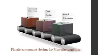
Material Selection Part Design Mould Shrinkage Plastic component design Plastic component design for Manufacturability
Introduction • Plastics component are prevalent in consumer and industrial segments for its strength to weight ratio, low cost and ease of manufacturability. • They have a clean surface finish, water and UV resistance, chemical resistance and corrosion resistance. • From bumpers in automotive, Computer Peripherals-Mice, keyboards, Medical equipment for its sterility, mobile components, packaging products – plastic component has its footprint.
Introduction • For a given component, there are many ways to manufacture. Some of the manufacturing processes for plastic parts are • Casting • Extrusion • Compression Moulding • Forming • Injection moulding • Rotational Moulding • Blow Moulding • Thermoforming • 3D Printing
Material Selection: • Polymer selection is always a tedious part in the product development phase. Mostly, product engineers rely on the vendors to advise a suitable variant of polymer for the product. • Based on the objectives and requirements pledged by the product’s operation and working environment – polymers are selected based on the level of Chemical and UV resistance, Temperature, Heat resistance, Flammability, Electrical and Mechanical capabilities, required surface finish and assembly ease suitable material are chosen. • Due to the day by day developments in polymer resins, the feasibility of manufacturing process for the material, its availability and cost are taken into account on selection.
Radius: • Internal sharp edges have to be avoided while designing the component. • All corners and edges are to be filleted and provided with the radius based on the thickness considered and the strength parameters required near the corners. • As a general thumb rule, the corners and edges are filleted with a radius of 0.9 to 1.2 times the nominal thickness
Wall Thickness : • Wall thickness is a primary element for the strength of the component and is also in the prospect of manufacturability. • Wall thickness has to be consistent to avoid most of the defects occurring during the manufacturing processes. In-consistent thicknesses affect mould flow, part formation and cooling. • Higher thickness may affect the flow and cooling of the flow. Radius and Rounded corners in the edges help proper filling in the mould.
Draft Angle: • Taper in the vertical walls of the component is called the draft angle. • Positive draft angle enables proper ejection of the component from the die without damage. • As a general thumb rule, the draft angle of 1 to 2 degrees is applied to the inner vertical walls.
Gate Location • Gates ensures proper resin flow and filling of the cavity in the mould. • Gates are positioned to effectively fill the cavity in the mould before the resin cools down. • Type of gate and its position varies based on the geometric complexity and has a high impact over the feasibility of producing the component without any defects.
Ribs • Plastic components with small wall thickness and requires mechanical strength – Ribs are provided to reinforce the walls and to reduce shrinking. • To eliminate white marks, 50 to 70 per cent of the wall thickness is considered for ribs.
Mould Shrinkage: • Generally, 20 per cent of the volume gets reduced from the cavity due to shrinkage while cooling. • Amorphous material shrinks lesser over crystalline polymers. Some of the parameters to consider to avoid shrinkage are – Polymer formulation, mould design, process temperature, melting temperature, cooling temperature, injection speed, time and pressure.
Conclusion : • Graphler Technologyproviding services like 3D to 2D Conversion Services, • CAD Conversion Services etc. • We have engineering experts specialized in CAD, FEA Services, Plastic Design, Plastic Part design, Pressure Vessel Analysis Services, Surface modellingand on 3D Modelling Services in India etc.