Download

1 / 17
230 likes | 702 Views
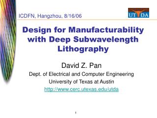
Design for Manufacturability. Prof. Shiyan Hu shiyan@mtu.edu Office: EERC 731. Outline. Manufacturability Basics CMP. Photo-Lithographic Process. optical. mask. oxidation. photoresist. photoresist coating. removal (ashing). stepper exposure. Typical operations in a single .

E N D
Design for Manufacturability Prof. Shiyan Hu shiyan@mtu.edu Office: EERC 731
Outline • Manufacturability Basics • CMP
Photo-Lithographic Process optical mask oxidation photoresist photoresist coating removal (ashing) stepper exposure Typical operations in a single photolithographic cycle (from [Fullman]). photoresist development acid etch process spin, rinse, dry step
Lithography Primer: Basics • The famous Raleigh Equation: : Wavelength of the exposure system NA: Numerical Aperture (sine of the capture angle of the lens, and is a measure of the size of the lens system) k1: process dependent adjustment factor • Exposure = the amount of light or other radiant energy received per unit area of sensitized material. • Depth of Focus (DOF) = a deviation from a defined reference plane wherein the required resolution for photolithography is still achievable. • Animation: http://www.microscopy.fsu.edu/primer/anatomy/numaperture.html
Numerical Aperture • NA=nsin n=refractive index for air, UB =1. Practical limit ≈ 0.93 • NA increase DOF decrease • Immersion lithography ? n>1 (e.g., water)
k1 • k1 is complex process depending on RET techniques, photoresist performance, etc • Practical lower limit ≈ 0.25 • Minimum resolvable dimension with 193nm steppers = 0.25*193/0.93 = 52nm Source: www.icknowledge.com
Layout 0.25µ 0.18µ 0.13µ 90-nm 65-nm Mask versus Printing Figures courtesy Synopsys Inc.
Design Rules Explosion Number of design rules per process node
CMP & Area Fill • Chemical-Mechanical Planarization (CMP) • Polishing pad wear, slurry composition, pad elasticity make this a very difficult process step silicon wafer slurry feeder wafer carrier polishing pad slurry polishing table • Area fill feature insertion • Decreases local density variation • Decreases the ILD thickness variation after CMP Post-CMP ILD thickness Features Area fill features
Density Control Objectives Objective for Design = Min-Fill [Wong et al, DAC’00] minimize total amount of added fill subject to UB on window density variation
Tiling and its Impact on PD The Tiling Problem: Given a layout and a CMP model, determine the location and amount of dummy features needed to achieve a planarity target, and then modify the layout accordingly.
Results from Tiling for STI - I Density and Post-CMP Topography Simulations for a DSP chip from Motorola: Shape Density Topography Original: max = 284A Tiled: max = 150A
CMP Topography variation T =HMAX-HMIN.. Observations Topography variation determines the depth of focus in lithography, an important factor of manufacturability. Topography variation is determined by the feature density distribution of the circuit layout. Feature density distribution varies with shuttle mask floorplans CMP Topography Variation
OPC/RET-Aware Routing [Huang, DAC’04; Mitra et al, DAC’05] Not OPC friendly OPC friendly