MAGNETO HYDRO DYNAMIC POWER GENERATION (MHD )
1.69k likes | 5.98k Views
MAGNETO HYDRO DYNAMIC POWER GENERATION (MHD ). CONTENTS. INTRODUCTION PRINCIPLE VARIOUS SYSTEMS ADVANTAGES FUTURE PROSPECTS. INTRODUCTION.

MAGNETO HYDRO DYNAMIC POWER GENERATION (MHD )
E N D
Presentation Transcript
CONTENTS • INTRODUCTION • PRINCIPLE • VARIOUS SYSTEMS • ADVANTAGES • FUTURE PROSPECTS
INTRODUCTION • Magneto hydrodynamics (MHD) (magneto fluid dynamics or hydro magnetics) is the academic discipline which studies the dynamics of electrically conductingfluids. Examples of such fluids include plasmas, liquid metals, and salt water. The word magneto hydro dynamics (MHD) is derived from magneto- meaning magnetic field, and hydro- meaning liquid, and -dynamics meaning movement. The field of MHD was initiated by Hannes Alfvén , for which he received the Nobel Prize in Physics in 1970 Hannes Alfvén
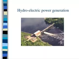
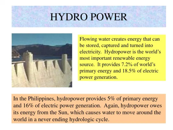
INTRODUCTION • 80 % of total electricity produced in the world is hydal, while remaining 20% is produced from nuclear, thermal, solar, geothermal energy and from magneto hydro dynamic (mhd) generator. • MHD power generation is a new system of electric power generation which is said to be of high efficiency and low pollution. In advanced countries MHD generators are widely used but in developing countries like INDIA, it is still under construction, this construction work in in progress at TRICHI in TAMIL NADU, under the joint efforts of BARC (Bhabha atomic research center), Associated cement corporation (ACC) and Russian technologists. • As its name implies, magneto hydro dynamics (MHD) is concerned with the flow of a conducting fluid in the presence of magnetic and electric field. The fluid may be gas at elevated temperatures or liquid metals like sodium or potassium.
INTRODUCTION • An MHD generator is a device for converting heat energy of a fuel directly into electrical energy without conventional electric generator. • In this system. An MHD converter system is a heat engine in which heat taken up at a higher temperature is partly converted into useful work and the remainder is rejected at a temperature. Like all heat engines, the thermal efficiency of an MHD converter is increased by supplying the heat at the highest practical temperature and rejecting it at the lowest practical temperature.
PRINCIPLES OF MHD POWER GENERATION • When an electric conductor moves across a magnetic field, a voltage is induced in it which produces an electric current. • This is the principle of the conventional generator where the conductors consist of copper strips. • In MHD generator, the solid conductors are replaced by a gaseous conductor, an ionized gas. If such a gas is passed at a high velocity through a powerful magnetic field, a current is generated and can be extracted by placing electrodes in suitable position in the stream. • The principle can be explained as follows. An electric conductor moving through a magnetic field experiences a retarding force as well as an induced electric field and current.
PRINCIPLES OF MHD POWER GENERATION • This effect is a result of FARADAYS LAWS OF ELECTRO MAGNETIC INDUCTION. • The induced EMF is given by Eind = u x B where u = velocity of the conductor. B = magnetic field intensity. • The induced current is given by, Jind = C x Eind where C = electric conductivity • The retarding force on the conductor is the Lorentz force given by Find = Jind X B
PRINCIPLES OF MHD POWER GENERATION • The electro magnetic induction principle is not limited to solid conductors. The movement of a conducting fluid through a magnetic field can also generate electrical energy. • When a fluid is used for the energy conversion technique, it is called MAGNETO HYDRO DYNAMIC (MHD), energy conversion. • The flow direction is right angles to the magnetic fields direction. An electromotive force (or electric voltage) is induced in the direction at right angles to both flow and field directions, as shown in the next slide.
PRINCIPLES OF MHD POWER GENERATION • The conducting flow fluid is forced between the plates with a kinetic energy and pressure differential sufficient to over come the magnetic induction force Find. • The end view drawing illustrates the construction of the flow channel. • An ionized gas is employed as the conducting fluid. • Ionization is produced either by thermal means I.e. by an elevated temperature or by seeding with substance like cesium or potassium vapors which ionizes at relatively low temperatures. • The atoms of seed element split off electrons. The presence of the negatively charged electrons makes the gas an electrical conductor.
VARIOUS MHD SYSTEMS • The MHD systems are broadly classified into two types. • OPEN CYCLE SYSTEM • CLOSED CYCLE SYSTEM • Seeded inert gas system • Liquid metal system
OPEN CYCLE SYSTEM • The fuel used maybe oil through an oil tank or gasified coal through a coal gasification plant • The fuel (coal, oil or natural gas) is burnt in the combustor or combustion chamber. • The hot gases from combustor is then seeded with a small amount of ionized alkali metal (cesium or potassium) to increase the electrical conductivity of the gas. • The seed material, generally potassium carbonate is injected into the combustion chamber, the potassium is then ionized by the hot combustion gases at temperature of roughly 2300’ c to 2700’c.
OPEN CYCLE SYSTEM • To attain such high temperatures, the compressed air is used to burn the coal in the combustion chamber, must be adequate to at least 1100’c. A lower preheat temperature would be adequate if the air is enriched in oxygen. An alternative is used to compress oxygen alone for combustion of fuel, little or no preheating is then required. The additional cost of oxygen might be balanced by saving on the preheater. • The hot pressurized working fluid living in the combustor flows through a convergent divergent nozzle. In passing through the nozzle, the random motion energy of the molecules in the hot gas is largely converted into directed, mass of energy. Thus , the gas emerges from the nozzle and enters the MHD generator unit at a high velocity.
OPEN CYCLE SYSTEM • The MHD generator is a divergent channel made of a heat resistant alloy with external water cooling. The hot gas expands through the rocket like generator surrounded by powerful magnet. During motion of the gas the +ve and –ve ions move to the electrodes and constitute an electric current. • The arrangement of the electrode connection is determined by the need to reduce the losses arising from the Hall effect. By this effect, the magnetic field acts on the MHD-generated current and produces a voltage in flow direction of the working fluid.
CLOSED CYCLE SYSTEM • Two general types of closed cycle MHD generators are being investigated. • Electrical conductivity is maintained in the working fluid by ionization of a seeded material, as in open cycle system. • A liquid metal provides the conductivity. • The carrier is usually a chemical inert gas, all through a liquid carrier is been used with a liquid metal conductor. The working fluid is circulated in a closed loop and is heated by the combustion gases using a heat exchanger. Hence the heat sources and the working fluid are independent. The working fluid is helium or argon with cesium seeding.
SEEDED INERT GAS SYSTEM • In a closed cycle system the carrier gas operates in the form of Brayton cycle. In a closed cycle system the gas is compressed and heat is supplied by the source, at essentially constant pressure, the compressed gas then expands in the MHD generator, and its pressure and temperature fall. After leaving this generator heat is removed from the gas by a cooler, this is the heat rejection stage of the cycle. Finally the gas is recompressed and returned for reheating. • The complete system has three distinct but interlocking loops. On the left is the external heating loop. Coal is gasified and the gas is burnt in the combustor to provide heat. In the primary heat exchanger, this heat is transferred to a carrier gas argon or helium of the MHD cycle. The combustion products after passing through the air preheated and purifier are discharged to atmosphere.
SEEDED INERT GAS SYSTEM • Because the combustion system is separate from the working fluid, so also are the ash and flue gases. Hence the problem of extracting the seed material from fly ash does not arise. The fuel gases are used to preheat the incoming combustion air and then treated for fly ash and sulfur dioxide removal, if necessary prior to discharge through a stack to the atmosphere. • The loop in the center is the MHD loop. The hot argon gas is seeding with cesium and resulting working fluid is passed through the MHD generator at high speed. The dc power out of MHD generator is converted in ac by the inverter and is then fed to the grid.
LIQUID METAL SYSTEM • When a liquid metal provides the electrical conductivity, it is called a liquid metal MHD system. • An inert gas is a convenient carrier • The carrier gas is pressurized and heated by passage through a heat exchanger within combustion chamber. The hot gas is then incorporated into the liquid metal usually hot sodium to form the working fluid. The latter then consists of gas bubbles uniformly dispersed in an approximately equal volume of liquid sodium. • The working fluid is introduced into the MHD generator through a nozzle in the usual ways. The carrier gas then provides the required high direct velocity of the electrical conductor.
LIQUID METAL SYSTEM • After passage through the generator, the liquid metal is separated from the carrier gas. Part of the heat exchanger to produce steam for operating a turbine generator. Finally the carrier gas is cooled, compressed and returned to the combustion chamber for reheating and mixing with the recovered liquid metal. The working fluid temperature is usually around 800’c as the boiling point of sodium even under moderate pressure is below 900’c. • At lower operating temp, the other MHD conversion systems may be advantageous from the material standpoint, but the maximum thermal efficiency is lower. A possible compromise might be to use liquid lithium, with a boiling point near 1300’c as the electrical conductor lithium is much more expensive than sodium, but losses in a closed system are less.
ADVANTAGES • The conversion efficiency of a MHD system can be around 50% much higher compared to the most efficient steam plants. Still higher efficiencies are expected in future, around 60 – 65 %, with the improvements in experience and technology. • Large amount of power is generated. • It has no moving parts, so more reliable. • The closed cycle system produces power, free of pollution. • It has ability to reach the full power level as soon as started. • The size if the plant is considerably smaller than conventional fossil fuel plants.
ADVANTAGES • Although the cost cannot be predicted very accurately, yet it has been reported that capital costs of MHD plants will be competitive to conventional steam plants. • It has been estimated that the overall operational costs in a plant would be about 20% less than conventional steam plants. • Direct conversion of heat into electricity permits to eliminate the turbine (compared with a gas turbine power plant) or both the boiler and the turbine (compared with a steam power plant) elimination reduces losses of energy. • These systems permit better fuel utilization. The reduced fuel consumption would offer additional economic and special benefits and would also lead to conservation of energy resources. • It is possible to use MHD for peak power generations and emergency service. It has been estimated that MHD equipment for such duties is simpler, has capability of generating in large units and has the ability to make rapid start to full load.
FUTURE PROSPECTS • It is estimated that by 2020, almost 70 % of the total electricity generated in the world will be from MHD generators. • Research and development is widely being done on MHD by different countries of the world. Nations involved: • USA • Former USSR • Japan • India • China • Yugoslavia • Australia • Italy • Poland