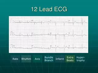
The 12-Lead EKG Chapter 12
160 likes | 569 Views
The 12-Lead EKG Chapter 12. Robert J. Huszar, MD Instructor Patricia L. Thomas, MBA, RCIS. Outline. Electrical Axes and Vectors The electrical current, vectors, and the lead axis The hexaxial reference figure The QRS axis Determination of Axis. Electrical Axes & Vectors.

The 12-Lead EKG Chapter 12
E N D
Presentation Transcript
The 12-Lead EKGChapter 12 Robert J. Huszar, MD Instructor Patricia L. Thomas, MBA, RCIS
Outline • Electrical Axes and Vectors • The electrical current, vectors, and the lead axis • The hexaxial reference figure • The QRS axis • Determination of Axis
Electrical Axes & Vectors • Instantaneous cardiac vector-the electrical current generated by the depolarization or repolarization of the atria or ventricles at any given moment • Graphically as an arrow that has magnitude, direction, and polarity • Length of the shaft of the arrow represents the magnitude of the electrical current • Orientation or position of the arrow indicates the direction of flow of the electrical current • The tip of the arrow represents the positive pole of the electrical current • The tail is the negative pole
Normal DepolarizationFigure 12-2 Interventricular Septum 1 & 2 Right Ventricle 3 Left Ventricle (thick lateral portion) 3 Left Ventricular (lateral/posterior/base) 4
The Hexaxial Reference Figure • Composite of the two triaxial reference figures (limb leads+ augmented leads) • Purpose is to determine the direction of the QRS axis • Each +& - pole is assigned a degree number 00 to 1800 • The top are given – numbers • The bottom are given + numbers • NOT TO BE CONFUSED WITH the - & + poles of the lead axes
Electrical Axis Calculation • Plotting of the net direction or the electrical axis • QRS axis is most important it is correlates with the anatomy of the heart • Pathophysiology causes a shift in the axis
Calculate the Axis • 1. Calculate the algebraic sum of QRS in Leads I & III • 2. Plot the vector results on a triaxial reference system • 3. Draw the perpendicular until Lead I & III cross. • 4. Draw a separate line from the center to the intersection of the two perpendiculars gives the electrical axis. • 5. Determine location (normal, RAD or LAD)
THE ENDOFCHAPTER 12 Hauszar Robert, Basic Dysrhythmias, Interpretation & Management, Third Edition, Mosby, Inc. 2002, pp. 171-187. Scheidt, Stephen M.D., Basic Electrocardiography,CIBA-GEIGY Pharmaceuticals, 1986 pp. 3,18,19