TECHNISONIC
TECHNISONIC. Understanding Noise in Airframe installations By: Walter Shawlee 2 Technisonic products are available from Dallas Avionics . Noise. What exactly is “noise”? Anything you didn’t want or expect to hear in the audio system. System Noise =. Equipment Noise Floor +

TECHNISONIC
E N D
Presentation Transcript
TECHNISONIC • Understanding Noise in Airframe installations • By: Walter Shawlee 2 • Technisonic products are available from Dallas Avionics.
Noise • What exactly is “noise”? • Anything you didn’t want or expect to hear in the audio system.
System Noise = • Equipment Noise Floor + • Cross-talk (de-selected audio) + • Ground Loop noise + • RF artifacts + • Coupled noise + • Acoustic Noise +
Noise is the Enemy • Installation costs and time are momentary… • But a bad install is forever. • Take the time to get everything as right as possible. • Understanding noise origins is critical.
Types of Noise • In-band audio frequency noise. • Cross-talk • Signal contamination • Inverter/Generator Contamination
Types of Noise • Out-of-Band RF Sources: • AM Comms • HF/SSB • FM Comms
RF Problems • Ship Issues can be multi-modal: • Radio to Radio Interference • Harmonic • Direct • Radio to Audio line rectification • Antenna Induced Standing Waves
Antennas • All simple monopole antennas assume they have a ground plane equal in radius to the height of the antenna. • Anything less results in substantial reflected power,and high standing waves on the coax cable. This dramatically worsens interference.
RF Solutions • Triaxial Cable, shield grounded at one end only. • Do not bundle RF feedlines with other cables. • Better antenna ground planes. • Better antenna spacing.
Mechanical-RF • The Main Rotor will modulate outgoing transmissions, and incoming reception, and change reflected power. • Antenna PLACEMENT is everything to fix this.
Antenna Issues • Bottom Mounts work best for AM Comms on helicopters.
RF Interference Rule • Once the RF interference appears as AUDIO, it is too late to suppress or correct it. It has to be suppressed in the RF mode.
Spacing & Proximity • There’s rarely enough room in general aviation aircraft...
10 kg in a 5 kg box • Sometimes it’s just not that easy…
Audio Wiring • Wiring topology and routing have a large bearing on audio system performance. • No amount of shielding can overcome design limits.
Audio Wiring • Access/A (floating ground) technology can provide a 20-30dB improvement in noise and cross-talk over even high end grounded systems. • That is 100-1000 times better.
Audio Wiring • Grounded audio returns are highly subject to GROUND LOOP noise. • This style interconnect was an early method of saving weight, complexity and wire, but offers the worst possible performance.
Ground Loops • How we wish aircraft worked:
Ground Loops • What really happens:
Ground Loops • The “frame ground” is alive with voltages caused by different loads.
Ground Loops • Attaching audio returns to ground contaminates the audio signal with every load current flowing through the airframe. • These induced voltages can be VERY large, and are a real problem especially for low level audio lines like microphones.
Ground Loops • Ground currents also inject CROSS-TALK, as every audio line returned though ground becomes mixed with every other audio signal.
Ground Loops • The answer is to LIFT audio lines from the airframe ground, and process them as floating signals. • This improves both noise and cross-talk significantly.
Composites • Composites have these problems: • RF shielding dramatically reduced. • Ground resistance dramatically increased. • Static discharge problems dramatically increased.
Victim Wiring • Wiring type determines susceptibility.
Victim Wiring • Un-shielded wiring, with a ground return is the MOST susceptible to both interference and ground loop noise. • Shielding, and lifting the ground return dramatically improves this. • Twisted pairs can be almost as effective as shielding, IF FLOATING.
Victim Modes • Inductive Coupling is CURRENT Driven
Victim Modes • The only real cure for Inductive Coupling is INCREASED SPACING. Remember the inverse-square law. • Shields (unless co-netic material) are totally ineffective.
Victim Modes • Inductive coupling sources: • Any high current line (AC or DC). • Any inverter/magnetic switching element. • Internal switching regulators.
Victim Modes • Capacitive coupling is VOLTAGE Driven.
Victim Modes • Shielding is effective for Capacitive Coupling, IF the shield is a true shield, and not carrying current. • Spacing is also effective.
Susceptibility Rules • Most Susceptible Wiring: • High Impedance • Un-shielded/poorly shielded. • Low Voltage
Summary • Use a system that minimizes audio problems for your specific task. • Wiring has to be appropriate in terms of shielding and ground connections. • Audio cable proximity to other systems is critical.
Summary • Never connect un-needed wiring. • Comms to rear stations. • Nav Inputs to non-flight stations. • Unterminated inputs
Finally • Every system has a noise floor determined by these factors: • Hardware design & topology • Cabling • Ground/composite issues.
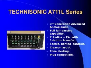
TECHNISONIC A711L Series • 3rd Generation Advanced Analog audio. • Full fail-passive capability. • 7 Radios + PA, with 1-button transfer. • Tactile, lighted controls. • Cleaner layout. • Tone alerting. • Plug compatible.
TECHNISONIC A711L series • Cosmetic Options. • NVG + flexible light. • Powersonix PA capability. • Nifty PA options. • Latent features. • Ideal mate to the TDFM-7300. • Address integrated NAV/COM packages.
ARTS-100 • Audio Radio Test System • Has it’s own high current power, can test or demo virtually all TIL products, all the way up to the TFM-7300. • Rack based, or stand alone.
TECHNISONIC • http://til.ca short and sweet. • Walter2@til.ca any time for audio questions. • Available from Dallas Avionics. • Reference stuff: http://www.sphere.bc.ca/test/data.html
TECHNISONIC • See us at BOOTH 103 / 801 • Thank you!