Download
1 / 8
80 likes | 151 Views
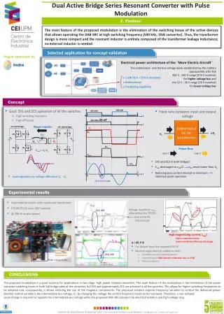
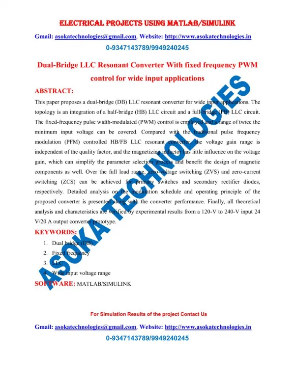
This paper proposes a dual-bridge (DB) LLC resonant converter for wide input applications. The topology is an integration of a half-bridge (HB) LLC circuit and a full-bridge (FB) LLC circuit. The fixed-frequency pulse width-modulated (PWM) control is employed and a range of twice the minimum input voltage can be covered. Compared with the traditional pulse frequency modulation (PFM) controlled HB/FB LLC resonant converter, the voltage gain range is independent of the quality factor, and the magnetizing inductor has little influence on the voltage gain, which can simplify the parameter selection process and benefit the design of magnetic components as well. Over the full load range, zero-voltage switching (ZVS) and zero-current switching (ZCS) can be achieved for primary switches and secondary rectifier diodes, respectively. Detailed analysis on the modulation schedule and operating principle of the proposed converter is presented along with the converter performance. Finally, all theoretical analysis and characteristics are verified by experimental results from a 120-V to 240-V input 24 V/20 A output converter prototype.

E N D
ELECTRICAL PROJECTS USING MATLAB/SIMULINK ELECTRICAL PROJECTS USING MATLAB/SIMULINK Gmail:asokatechnologies@gmail.com, Website: http://www.asokatechnologies.in 0-9347143789/9949240245 Dual-Bridge LLC Resonant Converter With fixed frequency PWM control for wide input applications ABSTRACT: This paper proposes a dual-bridge (DB) LLC resonant converter for wide input applications. The topology is an integration of a half-bridge (HB) LLC circuit and a full-bridge (FB) LLC circuit. The fixed-frequency pulse width-modulated (PWM) control is employed and a range of twice the minimum input voltage can be covered. Compared with the traditional pulse frequency modulation (PFM) controlled HB/FB LLC resonant converter, the voltage gain range is independent of the quality factor, and the magnetizing inductor has little influence on the voltage gain, which can simplify the parameter selection process and benefit the design of magnetic components as well. Over the full load range, zero-voltage switching (ZVS) and zero-current switching (ZCS) can be achieved for primary switches and secondary rectifier diodes, respectively. Detailed analysis on the modulation schedule and operating principle of the proposed converter is presented along with the converter performance. Finally, all theoretical analysis and characteristics are verified by experimental results from a 120-V to 240-V input 24 V/20 A output converter prototype. KEYWORDS: 1.Dual bridge (DB) 2.Fixed frequency 3.LLC 4.Wide input voltage range SOFTWARE: MATLAB/SIMULINK For Simulation Results of the project Contact Us Gmail:asokatechnologies@gmail.com, Website: http://www.asokatechnologies.in 0-9347143789/9949240245
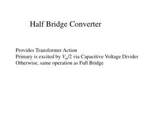
ELECTRICAL PROJECTS USING MATLAB/SIMULINK ELECTRICAL PROJECTS USING MATLAB/SIMULINK Gmail:asokatechnologies@gmail.com, Website: http://www.asokatechnologies.in 0-9347143789/9949240245 CIRCUIT DIAGRAM: Fig. 1. (a) Proposed DB LLC resonant converter. (b) Equivalent circuit when the proposed DB LLC resonant converter operates in the HB mode. (c) Equivalent circuit when the proposed DB LLC resonant converter operates in the FB mode. For Simulation Results of the project Contact Us Gmail:asokatechnologies@gmail.com, Website: http://www.asokatechnologies.in 0-9347143789/9949240245
ELECTRICAL PROJECTS USING MATLAB/SIMULINK ELECTRICAL PROJECTS USING MATLAB/SIMULINK Gmail:asokatechnologies@gmail.com, Website: http://www.asokatechnologies.in 0-9347143789/9949240245 EXPECTED SIMULATION RESULTS: Fig. 2. Measured steady-state voltage and currentwaveforms at full load with different input voltages. (a) Vin = 120 V; (b) Vin = 130 V; (c) Vin = 190 V; (d) Vin = 240 V. For Simulation Results of the project Contact Us Gmail:asokatechnologies@gmail.com, Website: http://www.asokatechnologies.in 0-9347143789/9949240245
ELECTRICAL PROJECTS USING MATLAB/SIMULINK ELECTRICAL PROJECTS USING MATLAB/SIMULINK Gmail:asokatechnologies@gmail.com, Website: http://www.asokatechnologies.in 0-9347143789/9949240245 Fig. 3. ZVS waveforms of switches Q1 and Q2 with the converter operating at (a) full load with 120 V input, (b) full load with 240 V input, (c) 10% load with 120 V input, and (d) 10% load with 240 V input. For Simulation Results of the project Contact Us Gmail:asokatechnologies@gmail.com, Website: http://www.asokatechnologies.in 0-9347143789/9949240245
ELECTRICAL PROJECTS USING MATLAB/SIMULINK ELECTRICAL PROJECTS USING MATLAB/SIMULINK Gmail:asokatechnologies@gmail.com, Website: http://www.asokatechnologies.in 0-9347143789/9949240245 Fig. 4. Experimental results of the DB LLC resonant converter with closed loop control in response to ramp changes in the input voltage Vin. (a) Ramp increase of the input voltage Vin from 130 to 190 V. (b) Ramp decrease of the input voltage Vin from 190 to 130 V. For Simulation Results of the project Contact Us Gmail:asokatechnologies@gmail.com, Website: http://www.asokatechnologies.in 0-9347143789/9949240245
ELECTRICAL PROJECTS USING MATLAB/SIMULINK ELECTRICAL PROJECTS USING MATLAB/SIMULINK Gmail:asokatechnologies@gmail.com, Website: http://www.asokatechnologies.in 0-9347143789/9949240245 Fig. 5. Experimental results of the DB LLC resonant converter with closed loop control in response to step changes in the load. (a) Step increase of load from light load to full load. (b) Step increase of load from full load to 10% load. Fig. 6. Measured power stage efficiency of the converter prototype for different input voltages. For Simulation Results of the project Contact Us Gmail:asokatechnologies@gmail.com, Website: http://www.asokatechnologies.in 0-9347143789/9949240245
ELECTRICAL PROJECTS USING MATLAB/SIMULINK ELECTRICAL PROJECTS USING MATLAB/SIMULINK Gmail:asokatechnologies@gmail.com, Website: http://www.asokatechnologies.in 0-9347143789/9949240245 CONCLUSION: A fixed-frequency-controlled DB LLC resonant converter with a wide input range has been proposed in this paper. In the proposed DBLLC resonant converter, two operating modes (HB and FB modes) are identified and utilized to regulate the output voltage within a wide input voltage range. The modulation strategy, operating principle and characteristics are investigated in depth. Compared with a conventional PFM-controlled LLC converter, the proposed DB LLC resonant converter adopts the fixed-frequency PWM control. The voltage gain range is independent of the quality factor Q and the magnetizing inductance has little impact on the dc voltage gain characteristics. Thus, the process of parameter design can be simplified and also a larger inductor ratio can be chosen to reduce the conduction loss. The structure and control strategy of the DB LLC resonant converter are simpler compared with conventional fixed- frequency TL LLC resonant converters. The performance of the proposed DB LLC resonant converter is experimentally verified on a 120–240 V input 24 V/20 A output converter prototype. All primary-side switches operate with ZVS and secondary-side diodes turn off with ZCS within wide input voltage and full-load ranges. Also, good dynamic performance with respect to input variations and load changes can be achieved under the closed-loop control. Therefore, the DB LLC resonant converter is a good candidate for wide input voltage applications. REFERENCES: [1] M.M. Jovanovi´c and B. T. Irving, “On-the-fly topology-morphing control efficiency optimization method for LLC resonant converters operating in wide input- and/or output-voltage range,” IEEE Trans. Power Electron., vol. 31, no. 3, pp. 2596–2608, Mar. 2016. For Simulation Results of the project Contact Us Gmail:asokatechnologies@gmail.com, Website: http://www.asokatechnologies.in 0-9347143789/9949240245
ELECTRICAL PROJECTS USING MATLAB/SIMULINK ELECTRICAL PROJECTS USING MATLAB/SIMULINK Gmail:asokatechnologies@gmail.com, Website: http://www.asokatechnologies.in 0-9347143789/9949240245 [2] J. Deng, C. C. Mi, R. Ma, and S. Li, “Design of LLC resonant converters based on operation- mode analysis for level two PHEV battery chargers,”IEEE Trans. Mechatronics, vol. 20, no. 4, pp. 1595–1606, Aug. 2015. [3] D. Moon, J. Park, and S. Choi, “New interleaved current-fed resonant converter with significantly reduced high current side output filter for EV and HEV applications,”IEEE Trans. Power Electron., vol. 30, no. 8, pp. 4264–4271, Jun. 2015. [4] F. Musavi, M. Craciun, D. S. Gautam, and W. Eberle, “Control strategies for wide output voltage range LLC resonant DC–DC converters in battery chargers,” IEEE Trans. Veh. Technol., vol. 63, no. 3, pp. 1117–1125, Jun. 2014. [5] C.W. Tsang, M. P. Foster, D. A. Stone, and D. T. Gladwin, “Analysis and design of LLC resonant converters with capacitor-diode clamp current limiting,” IEEE Trans. Power Electron., vol. 30, no. 3, pp. 1345–1355, Mar. 2015 For Simulation Results of the project Contact Us Gmail:asokatechnologies@gmail.com, Website: http://www.asokatechnologies.in 0-9347143789/9949240245