Download
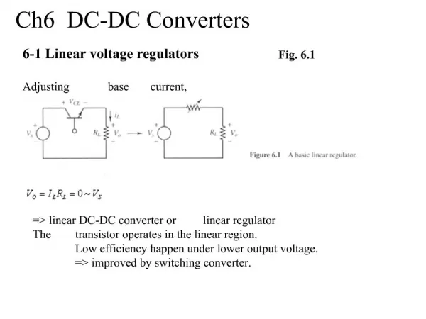
1 / 9
90 likes | 166 Views
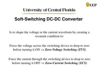
An electrolyzer is part of a renewable energy system and generates hydrogen from water electrolysis that is used in fuel cells. A dc-to-dc converter is required to couple the electrolyzer to the system dc bus. This paper presents the design of three soft-switched high-frequency transformer isolated dc-to-dc converters for this application based on the given specifications. It is shown that LCL-type series resonant converter (SRC) with capacitive output filter is suitable for this application. Detailed theoretical and simulation results are presented. Due to the wide variation in input voltage and load current, no converter can maintain zero-voltage switching (ZVS) for the complete operating range. Therefore, a two-stage converter (ZVT boost converter followed by LCL SRC with capacitive output filter) is found suitable for this application. Experimental results are presented for the two-stage approach which shows ZVS for the entire line and load range.

E N D
ELECTRICAL PROJECTS USING MATLAB/SIMULINK ELECTRICAL PROJECTS USING MATLAB/SIMULINK Gmail:asokatechnologies@gmail.com, Website: http://www.asokatechnologies.in 0-9347143789/9949240245 A Comparison of Soft-Switched DC-to-DC Converters for Electrolyzer Application ABSTRACT: An electrolyzer is part of a renewable energy system and generates hydrogen from water electrolysis that is used in fuel cells. A dc-to-dc converter is required to couple the electrolyzer to the system dc bus. This paper presents the design of three soft-switched high-frequency transformer isolated dc-to-dc converters for this application based on the given specifications. It is shown that LCL-type series resonant converter (SRC) with capacitive output filter is suitable for this application. Detailed theoretical and simulation results are presented. Due to the wide variation in input voltage and load current, no converter can maintain zero-voltage switching (ZVS) for the complete operating range. Therefore, a two-stage converter (ZVT boost converter followed by LCL SRC with capacitive output filter) is found suitable for this application. Experimental results are presented for the two-stage approach which shows ZVS for the entire line and load range. KEYWORDS: 1.DC-to-DC converters 2.Electrolyzer 3.Renewable energy system (RES) 4.Resonant converters. SOFTWARE: MATLAB/SIMULINK For Simulation Results of the project Contact Us Gmail:asokatechnologies@gmail.com, Website: http://www.asokatechnologies.in 0-9347143789/9949240245
ELECTRICAL PROJECTS USING MATLAB/SIMULINK ELECTRICAL PROJECTS USING MATLAB/SIMULINK Gmail:asokatechnologies@gmail.com, Website: http://www.asokatechnologies.in 0-9347143789/9949240245 BLOCK DIAGRAM: Fig. 1. Block diagram of a typical RES. For Simulation Results of the project Contact Us Gmail:asokatechnologies@gmail.com, Website: http://www.asokatechnologies.in 0-9347143789/9949240245
ELECTRICAL PROJECTS USING MATLAB/SIMULINK ELECTRICAL PROJECTS USING MATLAB/SIMULINK Gmail:asokatechnologies@gmail.com, Website: http://www.asokatechnologies.in 0-9347143789/9949240245 EXPECTED SIMULATION RESULTS: Fig. 2. Simulation waveforms for LCL SRC with capacitive output filter at full-load (2.4 kW) with Vin = 40V and Vo = 60V: inverter output voltage vab ; current through resonant tank inductor iLr ; switch currents (iS 1–iS 4 ); rectifier input voltage (vrectin ); voltage across and current through output rectifier diode DR1 . For Simulation Results of the project Contact Us Gmail:asokatechnologies@gmail.com, Website: http://www.asokatechnologies.in 0-9347143789/9949240245
ELECTRICAL PROJECTS USING MATLAB/SIMULINK ELECTRICAL PROJECTS USING MATLAB/SIMULINK Gmail:asokatechnologies@gmail.com, Website: http://www.asokatechnologies.in 0-9347143789/9949240245 Fig. 3. Simulation waveforms of Fig. 13 repeated for LCL SRC with capacitive output filter at 10% load with Vin = 40V and Vo= 60V. For Simulation Results of the project Contact Us Gmail:asokatechnologies@gmail.com, Website: http://www.asokatechnologies.in 0-9347143789/9949240245
ELECTRICAL PROJECTS USING MATLAB/SIMULINK ELECTRICAL PROJECTS USING MATLAB/SIMULINK Gmail:asokatechnologies@gmail.com, Website: http://www.asokatechnologies.in 0-9347143789/9949240245 Fig. 4. Experimental waveforms obtained for two stage converter cell (see Fig. 15) at full-load (2.4 kW) with Vin = 40V and Vo= 60V. (a) Voltage vSW across drain-to-source of boost switch (SW) and gating signal vgto the boost switch. (b) Inverter output voltage vab and current through resonant tank inductor iLr . (c) Rectifier input voltage vrectin and current through parallel inductor Lt, iLt . (d) Rectifier input voltage vrectin and secondary current isec. Scales: (a) vSW(40V/div) and vg(10V/div). (b) vab (100 V/div) and iLr (20A/div) (c) vrectin (100 V/div) and iLt (20A/div). (d) vrectin (100 V/div) and isec (20A/div). For Simulation Results of the project Contact Us Gmail:asokatechnologies@gmail.com, Website: http://www.asokatechnologies.in 0-9347143789/9949240245
ELECTRICAL PROJECTS USING MATLAB/SIMULINK ELECTRICAL PROJECTS USING MATLAB/SIMULINK Gmail:asokatechnologies@gmail.com, Website: http://www.asokatechnologies.in 0-9347143789/9949240245 . Fig. 5. Experimental waveforms of Fig. 17 repeated for Vin = 40V and Vo= 40V at Id= 10 A. Scales: (a) vSW (40V/div) and vg(10V/div). (b) vab (40V/div) and iLr (20A/div). (c) vrectin (100 V/div) and iLt (20A/div). (d) vrectin (100 V/div) and isec (20A/div). For Simulation Results of the project Contact Us Gmail:asokatechnologies@gmail.com, Website: http://www.asokatechnologies.in 0-9347143789/9949240245
ELECTRICAL PROJECTS USING MATLAB/SIMULINK ELECTRICAL PROJECTS USING MATLAB/SIMULINK Gmail:asokatechnologies@gmail.com, Website: http://www.asokatechnologies.in 0-9347143789/9949240245 Fig. 6. Experimental waveforms of Fig. 17 repeated for Vin = 60V and Vo= 40V at Id= 10 A. Scales: (a) vSW (40V/div) and vg(10V/div). (b) vab (40V/div) and iLr (20A/div). (c) vrectin (100 V/div) and iLt (20A/div). (d) vrectin (100 V/div) and isec (20A/div). For Simulation Results of the project Contact Us Gmail:asokatechnologies@gmail.com, Website: http://www.asokatechnologies.in 0-9347143789/9949240245
ELECTRICAL PROJECTS USING MATLAB/SIMULINK ELECTRICAL PROJECTS USING MATLAB/SIMULINK Gmail:asokatechnologies@gmail.com, Website: http://www.asokatechnologies.in 0-9347143789/9949240245 CONCLUSION: A comparison of HF transformer isolated, soft-switched, dc to- dc converters for electrolyzer application was presented. An interleaved approach with three cells (of 2.4kWeach) is suitable for the implementation of a 7.2-kW converter. Three major configurations designed and compared are as follows: 1) LCL SRC with capacitive output filter; 2) LCL SRC with inductive output filter; and 3) phase-shifted ZVS PWM full-bridge converter. It has been shown that LCL SRC with capacitive output filter has the desirable features for the present application. Theoretical predictions of the selected configuration have been compared with the SPICE simulation results for the given specifications. It has been shown that none of the converters maintain ZVS for maximum input voltage. However, it is shown that LCL-type SRC with capacitive output filter is the only converter that maintains soft-switching for complete load range at the minimum input voltage while overcoming the drawbacks of inductive output filter. But the converter requires low value of resonant inductor Lr for low input voltage design. Therefore, it is better to boost the input voltage and then use the LCL SRC with capacitive output filter as a second stage. When this converter is operated with almost fixed input voltage, duty cycle variation required is the least among all the three converters while operating with ZVS for the complete variations in input voltage and load. A ZVT boost converter with the specified input voltage (40–60 V) will generate approximately 100V as the input to the resonant converter for Vo = 60V. Therefore, we have investigated the performance of a ZVT boost converter followed by the LCL SRC with capacitive output filter. It was shown experimentally that the two-stage approach obtained ZVS for all the switches over the complete operating range and also simplified the design of resonant converter. For Simulation Results of the project Contact Us Gmail:asokatechnologies@gmail.com, Website: http://www.asokatechnologies.in 0-9347143789/9949240245
ELECTRICAL PROJECTS USING MATLAB/SIMULINK ELECTRICAL PROJECTS USING MATLAB/SIMULINK Gmail:asokatechnologies@gmail.com, Website: http://www.asokatechnologies.in 0-9347143789/9949240245 REFERENCES: [1] A. P. Bergen, “Integration and dynamics of a renewable regenerative hydrogen fuel cell system,” Ph.D. dissertation, Dept. Mechanical Eng., Univ. Victoria, Victoria, BC, Canada, 2008. [2] D. Shapiro, J. Duffy, M. Kimble, and M. Pien, “Solar-powered regenerative PEM electrolyzer/fuel cell system,” J. Solar Energy, vol. 79, pp. 544–550, 2005. [3] F. Barbir, “PEM electrolysis for production of hydrogen from renewableenergy sources,” J. Solar Energy, vol. 78, pp. 661–669, 2005. [4] R. L. Steigerwald, “High-frequency resonant transistor DC-DC converters,”IEEE Trans. Ind. Electron., vol. 31, no. 2, pp. 181–191, May 1984. [5] R. L. Steigerwald, “A Comparison of half-bridge resonant converter topologies,” IEEE Trans. Power Electron., vol. 3, no. 2, pp. 174–182, Apr. 1988. For Simulation Results of the project Contact Us Gmail:asokatechnologies@gmail.com, Website: http://www.asokatechnologies.in 0-9347143789/9949240245