0 likes | 3 Views
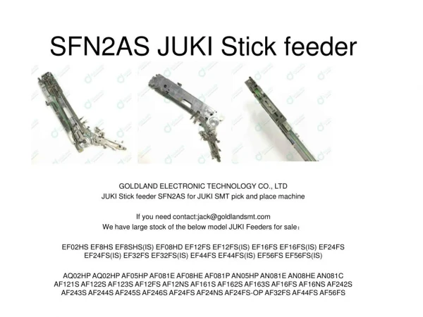
Discover unparalleled precision and efficiency with JUKI's SMT placement machines. Designed for speed without compromising on accuracy, our technology accelerates your production line, ensuring top-quality electronics assembly every time. Elevate your manufacturing process u2013 choose JUKI for the future of electronics production.<br><br>For more information, pls contact with us by www.smtfactory.com or info@smt11.com
E N D
Fast Smart Modular Mounter Specification Fast Smart Modular Mounter RS-1R 150mm conveyor extensions, upstream and downstream 50×50 ㎜ Model Item 250mm conveyor extensions, upstream and downstream Standard Conveyor specification Board size minimum maximum 650×370 ㎜ (single clamping) 1 buffer 950×370 ㎜ (double clamping) 1,200×370 ㎜ (double clamping) 1,100×370 ㎜ (double clamping) 3 buffers 360×370 ㎜ 600×370 ㎜ 500×370 ㎜ 25 ㎜ Component height Component size 0201*¹ ~□74 ㎜ /150×50 ㎜ Placement speed Optimum 47,000CPH IPC9850 31,000CPH Placement accuracy ±35μm (Cpk≧1) Feeder inputs max.112*² Power supply AC200 ~ 415V*³ 3-phases Apparent power 2.2kVA Operating air pressure 0.5±0.05MPa Air consumption Machine dimensions (W×D×H)*⁴ 200L/min for internal vacuum generator, 50 l/min with optional vacuum pump 1,500×1,810×1,440 ㎜ SOLDERING SOFTWARE STORAGE PRINTING INSPECTION PLACEMENT INSERTION 2,000×1,810×1,440 ㎜ 1,800×1,810×1,440 ㎜ Mass(approximately) 1,700kg *1 For metric 0201 compliance please contact us. *2 Using RF(RF08AS) feeders *3 A transformer unit (option) is necessary except AC 200 V. *4 D dimension does not include the front operation monitor. H dimension does not include signal tower. Option Fast Smart Modular Mounter RS-1R Recognitions system 10 / 27/ 54 mm view camera Oparations system Rear-side operation unit / keyboard (front only) Inspection function Coplanarity sensor / Component Verification System(CVS)*⁵ Conveyor Conveyor extention *⁶ / support pin / support sponge Electrical protection CE compatible specification / Ground-fault interrupter Force Control Force control unit / Force control nozzle Software*⁵ JaNets / IFS-NX / Flexline CAD Component handling Feeder Trolley RF feeder only / RF-EF dual servo *⁷) / Electric tape feeder (RF/EF*⁷) / EF feeder adapter*⁷/ and feeders Electric stick feeder*7(Type-N/Type-W) / Matrix tray server TR8SR, TR5SNX, TR5DNX / Matrix tray changer TR6SNV, TR6DNV / Dual tray server TR1RB / Nonstop oparation function / TrayHolder / IC collection belt / Tape reel mounting base(for RF / for EF) / Splicing jig / Electric Trolley Power Station PW02*⁸ RS-1R・RS-1 nozzles(with or without RFID tags) / Splicing tape / Big foot / Offset placement after solder screeen-printing Solder lighting / Mini-signal light / non-stop operation / FCS calibration jig / large ATC / Others vacuum pump *5 Please contact for details. *6 One side converyor extention is also possible. *7 When EF feeders adapt the an attachment of EF feeder, the EF feeder can use on RF/EF feeder trolley and fixed bank (rear side). Please inquire details. *8 Separate connection cables for each model are required. The RS-1R is an eco-friendly product which complies with JUKI ECO PRODUCTS standards for protecting the environment. ●The machine complies with the “JUKI Group Green Procurement Guidelines” on the use of hazardous substances, which is stricter than other restrictions, such as those of the RoHS Directive. For details of JUKI ECO PRODUCTS, refer to: https://www.JUKI.co.jp/eco_e/index.html *The RoHS Directive is an EU Directive limiting the use of 6 hazardous substances(lead, hexavalent chromium, mercury, cadmium,PBB and PBDE) in electrical and electronic equipment. The JUKI Green Procurement Guideline is the voluntarily established criteria to eliminate not only the aforementioned six substances, but also other ones which also adversely affect the environment. *Please refer to the product specifications for details. www.juki.co.jp JUKI AUTOMATION SYSTEMS INC www.jukiamericas.com JUKI AUTOMATION SYSTEMS GMBH www.juki-smt.com JUKI INDIA PVT LTD www.smtjukiindia.com JUKI AUTOMATION SYSTEMS CHINA www.jukichina.com JUKI SMT ASIA CO.,LTD July - 2019/Rev.06
Feature 3 Optimum line balance and highest throughput BASIC FEATURES Changing the RS-1 functionality does not require head replacement. The revolutionary design self-optimizes based on the production requirements. The RS-1R can reduce the workload on high speed. A line with two or more RS-1Rs can adjust to a wide variety of production requirements from high speed to high flexibility. 【For PCBs with high placement count】 【For PCBs with many complex components】 Class leading speed, up to 47,000 cph With optimal line banalce With optimal line banalce Newly developed "Takumi Head" with changing recognition sensor height Optimum line balance and highest throughput Wide component range from 0201 (metric) to large connectors and ICs Flexible mounter Chip only mounter Chip only mounter Chip only mounter Flexible mounter Chip only mounter Chip only mounter Chip only mounter Chip only mounter Flexible mounter RS-1R RS-1R Optimal for LED placement Feature 5 Feature 4 Nozzle traceability function Large Nozzle ATC OP OP High-Speed Smart Modular Mounter Changeable ATC plate supports nozzles up to 7x28mm. Large nozzles for large or heavy components are available. RFID tags are mounted on each nozzle to improve control and traceability. Nozzle maintenance can be monitored and traceability of performance is maintained. Feature 1 Class leading speed, up to 47,000 cph 【Placement speed*2】 Conventional machine*1 ●Class leading speed, up to 47,000 cph Maximum speed of up to 47,000 cph*. This is made possible by a revolutionary head design that reduces the travel time and distance for every placement. RS-1R 47,000CPH 42,000CPH Feature 6 Comparison to conventional machine 112% Wide component range from 0201 (metric) to large connectors and ICs *Optimum *1 RS-1 *2Optimum ●New RF feeders are smaller, thinner, and lighter The new RF feeders are smaller and lighter, but still maintain the same high degree of positional accuracy. The thinner width allows up to 112 feeder inputs.* RS-1R supports components from 0201*1(metric) up to 74mm square or 50x150 retangular parts. Component height up to 25mm. □20 □33.5 □50 □74 【Maximum number of feeders mounted*2】 Advanced functionality RS-1R component range BGA 112 units FBGA *1 With 10mm view camera Please contact in detail. *2Total for front and rear Big QFP 【Part correspondence power】 Lead Long CN 0201*2~□74mm 50×150mm SOT QFP SOPQFN Feature 2 DI ㎜ CN Self-Optimizing Smart Head 1608 AL CN *2 Please contact for details. 1005 0402 "Takumi head" that automatically optimizes it's height between 6 different positions based on component height. Tact time is optimized by keeping the head as close to the PCB as possible for the components placed. 0201 Card SlotBig AL CN 0603 Component density Feature 7 Optimal for LED placement 【Variable height of the laser sensor in accordance with the component height】 ●High-precision placement of diffusion lenses. RS-1R can use either vision or laser centering for diffusing lenses, depending on the component requirements. A wide range of lens styles can be placed. Diffusion lens ex : component height 20mm component height New Dynamic Height 8 nozzle placement head automatically adjusts height to optimize placement speed. This head adjusts automatically based on the components to be placed from 1mm to 25mm in 6 different positions (1・3・ 6・12・20・25mm). Determination of orientation 25㎜ レ ー ザ 20㎜ Laser ex : component height 6mm 12㎜ Diffusion lens placement Adhseive LED chip Orientation determination by laser recognition ●Long PCB Support Up to 650 x 370mm with single clamping. Up to 950 x 370mm with dual clamping, or up to 1200 x 370mm with optional conveyor extensions. 6㎜ 3㎜NEW Conveyor direction 1㎜ 2nd clamp placement area 1st clamp placement area PWB 1,200mm 650mm
Recognition Technology Productivity Component Recognition Technology (54, 27, 10mm field of view) Image OP Support sponge Bank specification can be selected OP Standard Component shape, lead and ball details are accurately captured using our VCS camera. Component problems such as missing ball detection or bent leads are also detected. A wide variety of components including BGAs and QFPs and many more are supported. Soft under board support reduces defects caused by PCB warpage. This unit uses soft pillars that will not damage components on the bottom side and do not require setup for each different PCB. They are easy to removed with a simple magnetic base. Feeder banks are available in either fixed or easy to replace trolley configurations.*1 ●360 degree part recognition technology Components that are supplied incorrectly can be corrected and accurately placed using 360 degree recognition technology. rear ■fixed bank specification □exchange truck specification*2 front Support sponge ●Front/back detection Components can be checked to see if they are face up/face down in the feeder. *1 Please contact detail. *2 Option Proactive maintenance warnings Flexible vision teaching Standard Standard ●Small chip recognition Components down to 0201 metric can be centered using the 10mm FOV camera. Dirty laser, low vacuum and upward looking camera condition are all checked prior to production starting to warn the operator of potential problems and prevent defects. Complicated programming of odd-shaped components is made easier by following step-by-step guidelines, reducing programming time significantly. Data is created automatically from a pictur of the component. Reflection recognition Reflection recognition Transmission recognition ●Three color recognition lighting The color of lighting can be changed to match the component requirements for stable, accurate centering. ●Wide component range Hundreds of nozzles to choose from and flexible vision to support difficut parts. Simplified data creation make it easy to handle complex components. Sample components and images 【Multi-component centering】 Laser condition check ●Faster image recognition ◎A new VCS unit can center up to 4 parts in a single image, reducing centering time by 25% with the 54mm field of view VCS. ◎Strobing vision can be used with the 10mm and 27mm FOV cameras for faster tact tim Flexible vision teaching Ease-of-operation improved by automatic component measurement Full virtual keyboard Sample images Up to 4 components are centered in a single image Standard Standard *KE-3010A Standard touchscreen keyboard for fast data entry. Component data can be programmed simply by typing approximate dimensions, type and packaging information. Accurate dimensions, number of leads and lead pitch are measured and programmed automatically by the machine. Component dimensions: Width JUKI's proprietary laser recognition technology is flexible, accurate and reliable. Laser Depth Components from 03015 metric to 50mm square SOP, PLCC, and QFP are supported. Laser centering provides stable, accurate centering and is not affected by variations in component color or shape. Component data is simple, making new part creation faster. Height Recognition algorithm Laser calculates the following data for each component: component shape Center Angle Width Pick Position Auto-correction Automated pre-production check list Standard Standard image of laser recognition The feeder pick position is automatically adjusted based on centering results to improve simultaneous picking and increasing throughput. Operators can use the automated pre-production check list to make sure all required operations have been completed. Ensures consistency and reduces overlooked operations. 8-nozzle simultaneous, on-the-fly centering for high-speed Laser The laser sensor is mounted on the head to minimize head travel. The head moves directly from the pick position to the placement position for the shortest travel time The path from picking to centering and placement is optimized for the fastest possible production speed Laser sensor integrated into placement head Setup preparation menu Feeder pick position auto-correct
Quality Other Options Incorrect component prevention Component Verification System (CVS) Tray Component Supply OP OP By measuring the resistance, capacitance, or polarity before production starts, the machine can prevent incorrect components from being placed. The new CVS unit can check six components simultaneously, reducing the check and changeover times. Several options are available to present components in trays. The compact width of the TR8 means there is still room for up to 20 8mm feeders on the same bank. A single tray holder and dual tray server are also available. The rear operation unit makes production more efficent by reducing the time the operator has to move around the line. Check the Resistance,Capacitance and Polarity before production starts. Prevents incorrect component/reel from being used Electrodes (A) used to check polarity or measure components Prevents incorrect component placement Reduce errors due to solder paste alignment Offset Placement After Solder Screen printing Matrix tray holder Dual tray server TR8S OP Stick feeder OP ●The OPASS function uses the machine's downward looking camera to check the location of solder paste vs. the pads and corrects the placement accordingly. This function reduces defects caused by misalignment of the paste on the pads. Single lane stick feeders install and remove as fast as tape feeders. Belt drive provides smooth, vibration free operation. LED indicates the feeder status. Placement based on solder location [A printing misalignment occurs] With OPASS function Solder Electric stick feeder Placement based on pad location Feeder Setup Stand Load Cell OP Pad OP Without OPASS function The feeder setup fixture is used to load reels offline quickly and easily. It is safer and easier to use than laying feeders on a table. Load cell measures the placement force precisely for each nozzle. The risk of damaging fragile components is reduced during both pick and placement. The load can be set individually for each part number. Manhattan phenomenon Displacement Reduction in the percentage defective ●Solder paste for fiducials Solder printed pads can be used in place of fiducials for circuit boards that do not have fiducials. This is especially helpful on long PCBs that require double clamping and do not have a fiducial in the appropriate area. Coplanarity sensor - checks balls and leads OP Data check on the monitor screen Mountable also on the rear side (front is standard) Feeder Setup Fixture for RF feeder Prevents placement of defective component by checking lead float of lead component and nick of ball component. High accurate and high speed coplanarity check will improve the products' reliability. FCS (Flex Calibration System) OP JUKI's highly regarded easy maintenance just got even easier! The optional FCS calibration jig is a simple to use system to re-calibrate placement accuracy. The machine automatically picks and places jig components, then measures the error and adjusts all necessary calibrations. (optional) Component direction Laser direction FCS image Coplanarity sensor BGA ball defect Lead float defect The IC collection belt Non-stop Operation OP OP Improved qualtiy using component checking Laser Component presence is monitored from pick to placement, reducing defects. The IC collection belt provides a safe method to handle rejected parts while also protecting them from further damage. Belt pitch can be set for different size parts. Non-stop operation allows the operator to replace feeders while the machine continues to run at full speed. ⑤Release check The laser checks the nozzle after placement to ensure the part was released on the PCB ①Tombstone detection Tombstone parts can be detected by ②Orientation check Component width/length ratio can be checked to ensure the part was picked in the correct orientation ③Dimension check Component width and length can be verified to esure it is the correct component ④Part drop check Component verified using the laser to ensure it has not fallen off the nozzle presence is laser and rejected Laser Laser Laser The IC collection belt