1 / 8

Tesla Powerwall 3 Datasheet - Halcol Energy

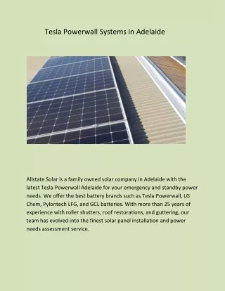
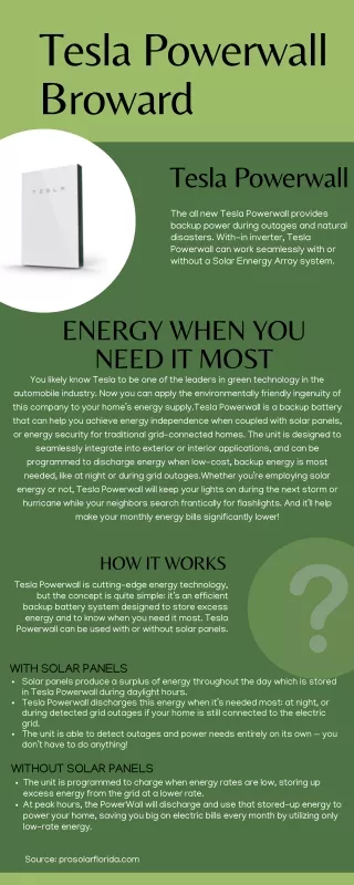
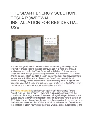
Download the Tesla Powerwall 3 Datasheet from Halcol Energy. Explore advanced energy storage solutions for Sunshine Coast solar systems.

Andrew56
Download Presentation

Tesla Powerwall 3 Datasheet - Halcol Energy

An Image/Link below is provided (as is) to download presentation Download Policy: Content on the Website is provided to you AS IS for your information and personal use and may not be sold / licensed / shared on other websites without getting consent from its author. Content is provided to you AS IS for your information and personal use only. Download presentation by click this link. While downloading, if for some reason you are not able to download a presentation, the publisher may have deleted the file from their server. During download, if you can't get a presentation, the file might be deleted by the publisher.

E N D

Presentation Transcript


  1. Powerwall 3 Power Everything — Powerwall 3 is a fully integrated solar and battery system, designed to accelerate the transition to sustainable energy. Customers can receive whole home backup, cost savings, and energy independence by producing and consuming their own energy while participating in grid services. Once installed, customers can manage their system using the Tesla App to customize system behavior to meet their energy goals. Powerwall 3 achieves this by supporting up to 20 kW DC of solar and providing up to 11.5 kW AC of continuous power per unit. It has the ability to start heavy loads rated up to 185 LRA, meaning a single unit can support the power needs of most homes. Powerwall 3 is designed for fast and efficient installations, modular system expansion, and simple connection to any electrical service. 2024

  2. Powerwall 3 Technical Specifications Model Number 1707000-xx-y System Technical Specifications Nominal Grid Voltage (Input & Output) 120/240 VAC Grid Type Split phase Frequency 60 Hz Solar to Battery to Home/Grid Efficiency 89% 1,2 Solar to Home/Grid Efficiency 97.5% 3 Supported Islanding Devices Gateway 3, Backup Switch, Backup Gateway 2 Connectivity Wi-Fi (2.4 and 5 GHz), Ethernet, Cellular (LTE/4G 4) Hardware Interface Dry contact relay, Rapid Shutdown (RSD) certified switch and 2-pin connector, RS-485 for meters AC Metering Revenue Grade (+/- 0.5%, ANSI C12.20) Protections Integrated arc fault circuit interrupter (AFCI), Isolation Monitor Interrupter (IMI), PV Rapid Shutdown (RSD) using Tesla Mid-Circuit Interrupters Customer Interface Tesla Mobile App Warranty 10 years Nominal Battery Energy 13.5 kWh AC 2 Battery Technical Specifications Nominal Output Power (AC) 5.8 kW 7.6 kW 10 kW 11.5 kW Maximum Apparent Power 5,800 VA 7,600 VA 10,000 VA 11,500 VA Maximum Continuous Current 24 A 31.7 A 41.7 A 48 A Overcurrent Protection Device 5 30 A 40 A 60 A 60 A Maximum Continuous Charge Current / Power 20.8 A AC / 5 kW Output Power Factor Rating 0 - 1 (Grid Code configurable) Maximum Output Fault Current (1 s) 160 A Maximum Short-Circuit Current Rating 10 kA Load Start Capability 185 LRA Power Scalability Up to 4 Powerwall 3 units supported Maximum Solar STC Input 20 kW Solar Technical Specifications Withstand Voltage 600 V DC PV DC Input Voltage Range 60 — 550 V DC PV DC MPPT Voltage Range 60 — 480 V DC MPPTs 6 Maximum Current per MPPT (Imp) Maximum Short Circuit Current per MPPT (Isc) 13 A 6 15 A 6 1 Typical solar shifting use case. 2 Values provided for 25°C (77°F), at beginning of life. 3.3 kW charge/discharge power. 3 Tested using CEC weighted efficiency methodology. 4 The customer is expected to provide internet connectivity for Powerwall 3; cellular should not be used as the primary mode of connectivity. Cellular connectivity subject to network operator service coverage and signal strength. 5 See Powerwall 3 Installation Manual for fuse requirements if using fuse for overcurrent protection. 6 Where the DC input current exceeds the MPPT rating, a jumper can be used to combine two MPPTs into a single input to intake DC current up to 26 A IMP / 30 A ISC. 2024 Powerwall 3 Datasheet 2

  3. Powerwall 3 Technical Specifications Operating Temperature –20°C to 50°C (–4°F to 122°F) 7 Environmental Specifications Operating Humidity (RH) Up to 100%, condensing Storage Temperature –20°C to 30°C (–4°F to 86°F), up to 95% RH, non- condensing, State of Energy (SOE): 25% initial Maximum Elevation 3000 m (9843 ft) Environment Indoor and outdoor rated Enclosure Rating NEMA 3R Ingress Rating IP67 (Battery & Power Electronics) IP55 (Wiring Compartment) Pollution Rating PD3 Operating Noise @ 1 m < 50 db(A) typical < 62 db(A) maximum 7 Performance may be de-rated at operating temperatures above 40°C (104°F). Certifications UL 1741, UL 9540, UL 9540A, UL 3741, UL 1741 PCS, UL 1741 SA, UL 1741 SB, UL 1973, UL 1699B, UL 1998, CSA C22.2 No. 0.8, CSA C22.2 No. 107.1, CSA C22.2 No. 330, CSA 22.3 No. 9, IEEE 1547, IEEE 1547A, IEEE 1547.1, CA Rule No.21 Compliance Information Grid Connection United States and Canada Emissions FCC Part 15 Class B, ICES 003 Environmental RoHS Directive 2011/65/EU Seismic AC156, IEEE 693-2005 (high) Fire Testing Meets the unit level performance criteria of UL 9540A Dimensions 1105 x 609 x 193 mm (43.5 x 24 x 7.6 in) 8 Mechanical Specifications Weight 130 kg (287 lb) Mounting Options Floor or wall mount 8 These dimensions include the glass front cover being installed on Powerwall 3. 1105 mm 193 mm 609 mm 2024 Powerwall 3 Datasheet 3

  4. Solar Shutdown Device Technical Specifications — The Solar Shutdown Device is a Mid-Circuit Interrupter (MCI) and is part of the PV system rapid shutdown (RSD) function in accordance with Article 690 of the applicable NEC. When paired with Powerwall 3, solar array shutdown is initiated by any loss of AC power. Electrical Specifications Model MCI-1 MCI-2 Nominal Input DC Current Rating (IMP) 13 A 13 A Maximum Input Short Circuit Current (ISC) 19 A 17 A Maximum System Voltage (PVHCS) 600 V DC 1000 V DC 9 Maximum Disconnect Voltage 10 600 V DC 165 V DC 9 Maximum System Voltage is limited by Powerwall to 600 V DC. 10 Maximum Disconnect Voltage is the maximum voltage allowed across each MCI in the open position (Rapid Shutdown Initiated). An individual MCI-2 has a voltage rating of 165V but in combination (connected in the same string) their voltage ratings are additive. Maximum Number of Devices per String 5 RSD Module Performance Control Power Line Excitation Passive State Normally Open Maximum Power Consumption 7 W Warranty 25 years Operating Temperature -40°C to 50°C (-40°F to 122°F) -45°C to 70°C (-49°F to 158°F) Environmental Specifications Storage Temperature –30°C to 70°C (–22°F to 158°F) –30°C to 70°C (–22°F to 158°F) Enclosure Rating NEMA 4X / IP65 Electrical Connections MC4 Connector Mechanical Specifications Housing Plastic Dimensions 125 x 150 x 22 mm (5 x 6 x 1 in) 173 x 45 x 22 mm (6.8 x 1.8 x 1 in) Weight 350 g (0.77 lb) 120 g (0.26 lb) Mounting Options ZEP Home Run Clip M4 Screw (#10) M8 Bolt (5/16") Nail / Wood screw Wire Clip UL 1741 PVRSE, UL 3741, PVRSA (Photovoltaic Rapid Shutdown Array) Compliance Information Certifications External System Shutdown Switch or Powerwall 3 Enable Switch RSD Initiation Method UL 3741 PV Hazard Control (and PVRSA) Compatibility See UL 3741 Application Addendum 2024 Powerwall 3 Datasheet 4

  5. Gateway 3 — Tesla Gateway 3 controls connection to the grid in a Powerwall system, automatically detecting outages and providing seamless transition to backup power. It provides energy monitoring that is used by Powerwall for solar self-consumption, time-based control, and backup operation. Performance Specifications Model Number 1841000-x1-y AC Meter +/- 0.5% Nominal Grid Voltage 120/240 V AC Communication CAN Grid Configuration Split phase User Interface Tesla App Grid Frequency 60 Hz Backup Transition Automatic disconnect for seamless backup Continuous Current Rating 200 A Overcurrent Protection Device 100–200 A Service entrance rated Eaton CSR, BWH, or BW, or Square D QOM breakers Maximum Supply Short Circuit Current 22 kA with Square D or Eaton main breaker 25 kA with Eaton main breaker 11 Internal Panelboard 200 A 8-space/16 circuit breakers Eaton BR, Siemens QP, or Square D HOM breakers rated to 10–125A IEC Protective Class Class I Overvoltage Category Category IV 11 Only Eaton CSR or BWH main breakers are 25 kA rated. Warranty 10 years Environmental Specifications Operating Temperature –20°C to 50°C (–4°F to 122°F) Operating Humidity (RH) Up to 100%, condensing Maximum Elevation 3000 m (9843 ft) Environment Indoor and outdoor rated Enclosure Type NEMA 3R Compliance Information Certifications UL 67, UL 869A, UL 916, UL 1741 PCS, CSA 22.2 107.1, CSA 22.2 29 Emissions FCC Part 15, Class B, ICES 003 Mechanical Specifications Dimensions 660 x 411 x 149 mm (26 x 16 x 6 in) Weight 16.3 kg (36 lb) Mounting options Wall mount 660 mm 149 mm 411 mm 2024 Powerwall 3 Datasheet 5

  6. Backup Switch — The Tesla Backup Switch controls connection to the grid in a Powerwall system, and can be easily installed behind the utility meter or in a standalone meter panel downstream of the utility meter. The Backup Switch automatically detects grid outages, providing a seamless transition to backup power. It communicates directly with Powerwall, allowing home energy usage monitoring from any mobile device with the Tesla app. Model Number 1624171-xx-y Performance Specifications Continuous Load Rating 200 A, 120/240 V split phase Maximum Supply Short Circuit Current 22 kA with breaker 12 Communication CAN AC Meter +/- 0.5% Expected Service Life 21 years Warranty 10 years 12 Breaker maximum supply short circuit current rating must be equal to or greater than the available fault current. Operating Temperature –40°C to 50°C (–40°F to 122°F) Environmental Specifications Storage Temperature –40°C to 85°C (–40°F to 185°F) Enclosure Rating NEMA 3R Pollution Rating PD3 Safety Standards USA: UL 414, UL 414 SB, UL 2735, UL 916, CA Prop 65 Compliance Information Emissions FCC Part 15, Class B, ICES 003 Dimensions 176 x 205 x 74 mm (6.9 x 8.1 x 2.9 in) Mechanical Specifications Weight 2.8 lb Meter and Socket Compatibility ANSI Type 2S, ringless or ring type External Service Interface Contactor manual override 13 Reset button Conduit Compatibility 1/2-inch NPT 13 Manually overrides the contactor position during a service event. 176 mm 204.86 205 mm 74 mm 74 2024 Powerwall 3 Datasheet 6

  7. Backup Gateway 2 — Backup Gateway 2 controls connection to the grid when paired with Powerwall 3, automatically detecting outages and providing seamless transition to backup power. Backup Gateway 2 also provides energy metering for solar self-consumption, time-based control, and backup operation. In this system configuration, Powerwall 3 acts as the Site Controller, with the Backup Gateway 2 Site Controller disabled. Model Number 1232100-xx-y User Interface Tesla App Performance Specifications AC Voltage (Nominal) 120/240 V Operating Modes Support for solar self- consumption, time-based control, and backup Feed-in Type Split phase Grid Frequency 60 Hz Backup Transition Automatic disconnect for seamless backup Current Rating 200 A Modularity Supports up to 10 AC- coupled Powerwalls Maximum Supply Short Circuit Current 10 kA 14 Optional Internal Panelboard 200 A 6-space / 12 circuit breakers Siemens QP or Square D HOM breakers rated 10 - 80A or Eaton BR breakers rated 10 - 125A Overcurrent Protection Device 100 - 200 A, Service entrance rated Overvoltage Category Category IV Internal Primary AC Meter +/- 0.2% Warranty 10 years 14 When protected by Class J fuses, Backup Gateway 2 is suitable for use in circuits capable of delivering not more than 22kA symmetrical amperes. Internal Auxiliary AC Meter +/- 2% Primary Connectivity Ethernet, Wi-Fi 15 Cellular connectivity subject to network operator service coverage and signal strength. Secondary Connectivity Cellular (3G, LTE/4G) 15 Operating Temperature –20°C to 50°C (–4°F to 122°F) Environmental Specifications Operating Humidity (RH) Up to 100%, condensing Maximum Elevation 3000 m (9843 ft) Environment Indoor and outdoor rated Enclosure Type NEMA 3R Certifications UL 67, UL 869A, UL 916, UL 1741 PCS, CSA 22.2 0.19, CSA 22.2 205 Compliance Information Emissions FCC Part 15, Class B, ICES 003 380 mm (15 in) 127 mm (5 in) 149 mm Dimensions 660 x 411 x 149 mm (26 x 16 x 6 in) Mechanical Specifications 411 mm Weight 20.4 kg (45 lb) Mounting options Wall mount, Semi-flush mount 660 mm 584 mm (23 in) 2024 Powerwall 3 Datasheet 7

  8. Powerwall 3 Example System Configurations Powerwall 3 with Gateway 3 Whole Home Backup Powerwall 3 with Backup Switch Whole Home Backup Powerwall 3 with Backup Gateway 2 Partial Home Backup 2024 Powerwall 3 Datasheet 8

More Related