Download
1 / 7

E N D
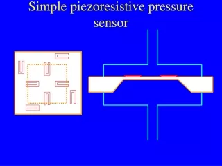
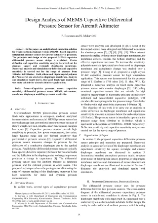
International Journal of Applied Physics and Mathematics, Vol. 2, No. 1, January 2012 Design Analysis of MEMS Capacitive Differential Pressure Sensor for Aircraft Altimeter P. Eswaran and S. Malarvizhi sensor were analyzed and developed [1]-[13]. Most of the developed sensors were designed and fabricated to measure the absolute pressure [3], [5], [8], [10], [11]. When external pressure is applied to these sensor diaphragm membranes, the membrane deflects towards the bottom electrode and the effective capacitance increases. To increase the sensitivity, polymide materials (polymer) have been used as diaphragm membrane and capacitance change was studied over a pressure range [3]. Young et al. proposed a single crystal 3C-SiC capacitive pressure sensor for high temperature application. This sensor was demonstrated for the pressure range of 1100mbar to 1760 mbar [14]. G. Men, W.H. Ko presented a numerical analysis on touch mode capacitive pressure sensor with circular diaphragm [9]. D.C.Catling examined capacitive sensors that are suitable for high sensitive measurement of barometric pressure on mars (few millibars) and demonstrated capacitive prototype, with circular silicon diaphragm for the pressure range from 0mbar to 40mbar with high sensitivity at pressure 0-10mbar [8]. The objective of this work is to carry out an analysis on centre deflection on diaphragm membrane and capacitance sensitivity to measure a pressure below the ambient pressure (1013mbar). The pressure sensor is intended to operate in the pressure range from 100mbar to 1140mbar, which is equivalent to the altitude of 50000ft to -1000ft respectively. Deflection sensitivity and capacitive sensitivity analysis was carried out for the above range of pressure. Abstract—In this paper, an analytical and simulation solution for Microelectromechanical systems (MEMS) based capacitive differential pressure sensor for aircraft altimeter is proposed. The principle and design of the proposed MEMS capacitive differential pressure sensor design is explained. Centre deflection and capacitive sensitivity analysis is carried out for circular, square and rectangle diaphragm membrane. Numerical analysis and simulation on deflection and capacitive sensitivity is carried out for the range of pressure from 100mbar to1100mbar. Gold, silicon and Liquid crystal polymer (LCP) material are selected as diaphragm membrane. Analysis and simulation result shows, that gold diaphragm membrane was more suitable for aircraft altimeter applications. Index Terms—Capacitive pressure sensor, capacitive sensitivity, differential pressure sensor MEMS, microsensor, membrane diaphragm modeling, pressure sensitivity. I.INTRODUCTION A. Overview Micromachined MEMS piezoresistive pressure sensor finds wide applications in aerospace, medical, analytical instrumentation and commercial. MEMS pressure sensor has more advantage than conventional pressure sensor because of its low weight, low cost, reliable, smart function and occupies less space [1]. Capacitive pressure sensors provide high sensitivity to pressure, low power consumption, low noise, large dynamic range and low thermal sensitivity than piezoresistive pressure sensors [2]. Capacitive differential pressure sensor measures changes in pressure by the deflection of a conductive diaphragm due to the applied pressure. Parallel plate differential pressure sensors typically have spacer (dielectric separator) between the two electrodes and the deflection in the diaphragm due to change in pressure produces a change in capacitance [3]. The differential pressure sensor uses the ambient pressure as reference pressure and the external pressure as other source. This proposed technique reduces the package cost, eliminating the need of vacuum sealing of the diaphragm; moreover it has high sensitivity for static measurements. C. Organization of Paper In section 2, the proposed capacitive differential pressure sensor principle and operation are presented. Numerical analysis on centre deflection of the diaphragm membrane and capacitance sensitivity for square, rectangle and circular diaphragm membrane are discussed in section 3. International standard atmosphere pressure model, structure layer model of the proposed sensor, properties of diaphragms membrane materials and dimensions of sensor structure and diaphragm membrane are illustrated in section 4. Section 5 discusses the analytical and simulated results with conclusion. and dynamic pressure II.PROPOSED DIFFERENTIAL PRESSURE SENSOR The differential pressure sensor uses the pressure difference between two pressure sources. The cross-section diagram of the differential pressure capacitance pressure sensor in undeformed condition is shown in Fig. 1. The diaphragm membrane with edges built in, suspended over a sealed cavity on a silicon nitrate substrate. In this design, the cavity is sealed with local ambient pressure which is acting B.Literature Review In earlier work, several types of capacitance pressure Manuscript received December 09, 2011; revised December 30, 2011. P. Eswaran is with Department of Electronics and Communication Engineering, SRM University, Kattankulathur, Chennai, Tamilnadu,, India. 603203 (e-mail: eswaran.p@ktr.srmuniv.ac.in). S. Malarvizhi is with Department of Electronics and Communication Engineering, SRM University, Kattankulathur, Chennai, Tamilnadu, India. 603203. 14
International Journal of Applied Physics and Mathematics, Vol. 2, No. 1, January 2012 deflection at point (x, y), E is young modulus,υis Poisson’s ratio and Fis a stress function and h is the thickness of the diaphragm. The set of governing equation for circular plate under load for diaphragm membrane in non touch operation are as follows [9]. dN r N dr on one side of the diaphragm. The external pressure will act on the other side of the diaphragm membrane; therefore the measured pressure will be represented in gauge pressure. The element of the capacitive pressure sensor is an equivalent parallel plate capacitor with champed edges, where the diaphragm would deform responding to a differential pressure applied to two sides of the diaphragm [10]. The capacitance C=εA/d, where ε is the permittivity of the dielectric of medium between the two plates, A is the effective area of the electrode plate and d is the gap between the two plates. The upper plate of the capacitor which forms one of the electrodes deforms, due to differential pressure between the external pressure and the ambient pressure inside the chamber. The diaphragm tends to deflects outward if the external pressure is less than the ambient pressure; Cross section of differential pressure capacitive pressure sensor with deformed condition as shown in the Fig. 2. + − r N (3) r t ⎛ ⎜ ⎝ ⎞ ⎟ ⎠ r ∫ 3 2 d w dr 1 r dr d w dw dr + ⋅ = + D N PErdr r 3 2 (4) 0 ( ) 2 + d N N Eh dw ⎛ ⎜ ⎝ ⎞ ⎟ ⎠ + = r dr t r 0 2 dr (5) where r is radius, P is pressure on diaphragm, E is young’s modules, h is thickness of plate, v is Poisson’s ratio, w is the deflection in the direction perpendicular in radial direction, Nr is tensile force per unit length in radial direction, Nt is tensile force per unit length in tangential direction and D is Flexural rigidity. 3 Eh = D − 2 12(1 ) v (6) Fig. 1. Cross section of differential pressure capacitive pressure sensor (undeformed). The centre deflection of circular diaphragm is calculated as [15]. 4 Pr 1 0.488 64 1 + = ⋅ w 0 2 0 w D 2 h (7) ( ) − 4 2 Pr 1 v = w 0 3 16 Eh (8) 2)For Square Diaphragm Membrane The governing differential equation for the deflection of thin plate given by [15], [16]. 2 2 2 x x y ∂ ∂ ∂ ∂ where D is the flexural rigidity, by solving with boundary condition, where all sides of the sensor diaphragm are built in, that is w w n ∂ Fig. 2. Cross section of differential pressure capacitive pressure sensor (deformed). III.NUMERICAL ANALYSIS ∂ ∂ ∂ 2 w w w y P D + + = 2 2 A.Analysis on Deflection Sensitivity 1)For Circular Diaphragm Membrane The general equation for deflection of thin plate in the x-y plan can be expressed [15]. (9) ⎡ ⎢ ⎢ ⎣ ⎤ ⎥ ⎥ ⎦ (1) 2 ⎛ ⎜ ⎝ ⎞ ⎟ ⎠ ∂ ∂ ∂ ∂ ∂ ∂ ∂ ∂ 4 4 4 2 2 2 F x F F w w x w y ∂ + + = − ⋅ 2 x y ∂ ∂ x y ∂ ∂ ∂ ∂ = = 4 2 4 2 y 0, 0 (10) ⎡ ⎢ ⎤ ⎥ ⎦(2) ∂ ∂ where D is flexural rigidity, differential pressure between two sides of a diaphragm, w is ∂ ∂ ∂ ∂ ∂ ∂ ∂ ∂ ∂ ∂ ∂ 4 4 4 2 2 2 2 2 2 F x F F h D h ⎣ P F x F F x y ∂ ∂ w F w + + = + ⋅ + − ⋅ 2 2 where n is the normal vector direction along the sides of the sensor diaphragm. The diaphragm deflection, w(x, y), for a square diaphragm is given by the superposition of the deflection due to the applied pressure w1(x, y), which is due to the bending x y ∂ ∂ x y ∂ ∂ x y ∂ ∂ 4 2 2 4 2 2 2 2 y y = − 3 2 , P is the D Eh 12(1 v ) 15
International Journal of Applied Physics and Mathematics, Vol. 2, No. 1, January 2012 moments generated from edges restrictions, w2(x, y), both under simply supported edge conditions [15], [16]. Given the following variables M h y σ = 6 y 2 (20) The maximum deflection of the diaphragm is the centre of diaphragm. We get the maximum deflection by superposition, that is max 1 w w = + ( 0.00406 w PL D = , 0.00126 w PL D = . If the instead of D, then the maximum deflection became, Obviously the maximum diaphragm deflection is linearly proportional to applied pressure. = + ( , ) w x y ( , ) w x y ( , ) w x y (11) 1 2 w . We can get π π π 2 w m m x L m y L = = = m , x , y , ) (12) 0.00280 = − 4 , 4 PL D 10,0 2 2 − 4 3 2 is used Eh 12(1 v ) max 2 Eh = (13) D − 2 12(1 ) v = = − − ( , ) f x y cos( )( sinh( ) x y y m tanh( )cosh( ) m y (14) 4 )PL Eh = υ 2 w 0.01512(1- (21) ( , ) f y x cos( )( sinh( ) y y x m tanh( )cosh( ) m x max 3 The deflection of diaphragm can be expressed as 3)For Rectangular Diaphragm Membrane The diaphragm centre deflection w(x, y) for rectangle diaphragm of Ref. [15] is given by − m 1 ( 1) − ∞ 4 4 π PL 2 ∑ = × ( , ) w x y cos( ) x 1 5 5 D m 4 Pb Eh 1,3,5 = m = α w ⎛ ⎜ ⎝ ⎞ ⎟ ⎠ + m tanh( ) 2 2cos( ) m y max 3 − + (22) (15) 1 cosh( ) y sinh( ) y x 2cosh( ) m ( ) − α = × × − 3 2 (23) 1.26 10 12 1 v − m 1 − − ∞ 4 2 PL D ( 1) cosh( ) 2 ∑ = × ( , ) w x y e TABLEI:COEFFICIENT Α FOR DIFFERENT RATIO OF B/ADIMENSION OF RECTANGULAR MEMBRANE DIAPHRAGM [15]. 2 m π 5 2 m m 1,3,5 = m ) ( where L , E ,h ,v is diaphragm length, Young’s modulus, diaphragm thickness, and Poisson’s ratio respectively. Coefficients m e are derived from the same procedure of Ref. [15] and we can get e1 = -0.372, e3 = -0.379, e5 =-0.0175, e7 =-0.0082, e9 =-0.00428, e11=0.00243,e13= 0.00147, e15 = 0.0009, e17 = 0.0006, and e19 = 0.0004 Then, the bending moment Mx and My are calculated by means of w M D x ∂ ⎝ + ( , ) f x y ( , ) f y x (16) where D, P, α, wmax(x, y) is flexural rigidity, pressure in MPa, coefficient of the rectangle thin plate and centre deflection. Where b/a=1 for square diaphragm, where a and b are the width and length of the rectangle plate. B.Analysis on Capacitance Sensitivity Measurement 1)For Circular Diaphragm Membrane The capacitive sensitivity for the pressure can be calculated as [13]. ε − ε dA w r A d ∫∫ Δ = C C − = − C 0 d ( ) A (24) ⎛ ⎜ ⎞ ⎟ ⎠ (17) ∂ ∂ ∂ 2 2 w = − + v x ε 2 2 y ∫∫ = θ C rdrd − d w r ( ) (25) ⎛ ⎜ ⎝ ⎞ ⎟ ⎠ (18) ∂ ∂ ∂ 2 2 w w x ∂ = − + M D v 2 ⎡ ⎢ ⎢ ⎣ ⎤ ⎥ ⎥ ⎦ (26) 2 y 4 ⎛ ⎜ ⎝ ⎞ ⎟ ⎠ 2 2 PA r A y ( ) = − w r 1 64 D The diaphragm plates are stress magnifying device. Since the diaphragm plate is sensitive to stress, it is necessary to evaluate the stress distribution of a plate. The stress can be calculated by where C is the capacitance corresponds to differential pressure P, Co is the capacitance at zero differential pressure. εris the relative permittivity of the dielectric wall separates the top and bottom electrodes, A is the area of the plate, and w(r) is the centre deflection corresponds to the differential pressure. d, r , D is distance between the electrode, radius of M h σ = x 6 x 2 (19) 16
International Journal of Applied Physics and Mathematics, Vol. 2, No. 1, January 2012 the diaphragm and flexural rigidity respectively. For circular diaphragm sensor the effective capacitance, the fixed capacitance constituted by Sidielectric and variable capacitance with air dielectric is given in equation (27) to (32). ( ) ε ε × 2 l b D D = r 0 a t (34) C Dielectric d ( ) ε ε l D b × +Δ = r 0 D t a (35) C = + Air C C C d (27) d eff Dielectric Air where l is the length of the diaphragm wall, ab is the inner ε ε A = d r 0 C (28) t D is the wall thickness of the D is the height of dielectric separating the Dielectric width of the (cavity), D d diaphragm, d ε A +Δ (29) = − 0 ε is the permittivity of rε is the dielectric permittivity of Siand centre displacement of diaphragm with reference zero differential pressure acting on diaphragm. × r a C 12 f m 8.854 10 D is the change in electrodes, , Air D d d d = − A A A (30) d T a = π 2 (31) T A r 0 = π 2 A r (32) a i Fig. 4. Top view of rectangle dimension sensor spacer structure. Fig. 3. Top view of Circular dimension sensor spacer structure. IV.SIMULATION MODEL Fig. 3 Shows a lateral sectional view of circular dimension sensor dielectric spacer structure. From the above equations where the area of the circular diaphragm separated by air as dielectric; A.Proposed Structure of Capacitive Differential Pressure Sensor T A is the total area of the circular diaphragm; A is A d A is the area of the circular diaphragm under dielectric, ir is the inner radius of diaphragm with air gap,0r is the outer radius of diaphragm. The proposed capacitance pressure sensor was designed with two electrodes separated by a dielectric medium, a hollow Si substrate as dielectric with wall thickness lateral sectional view of dielectric wall is shown in Fig. 3. Therefore the effective capacitance t D . The C of this sensor can eff Fig. 5. Cross section Sideview of sensor structure. The capacitive differential pressure sensor made up of four layers. Fig. 5. Shows the sectional view of sensor structure layers. Silicon material (Si) is used as a constraint base layer at with thickness of 100μm, a thin film of gold material deposited over Sibase layer by CVD process (chemical vapor deposition) with a thickness of 1µm, which form one of the electrode of capacitive pressure sensor. A Sispacer side wall serves as two purpose, used to separate the top and bottom electrode of the capacitive sensor and it act as a fixed solid dielectric medium with a permittivity of εr=11.6. The cavity is sealed with a diaphragm membrane with the be calculated by two sections, one with a fixed capacitance CDielectricobtained with fixed dielectric wall and the other with capacitance CAir due to the differential pressure acting on the diaphragm membrane area with air as dielectric. It is given in the equation (27). C C = + C (33) eff Dielectric Air 2)For Square and Rectangle Diaphragm Membrane The effective capacitance of the sensor is given by the sum of the capacitance constituted by CDielectric and CAir was given in equation (34) and (35) respectively. 17
International Journal of Applied Physics and Mathematics, Vol. 2, No. 1, January 2012 thickness of 3 μm and 5μm (same value is used in analysis) with atmospheric pressure inside. The top layer works in two ways, as diaphragm is subjected to differential pressure and the diaphragm itself acts as one of the electrode parallel plate of capacitive pressure sensor. numerical values modeling and simulation was carried out with Intellisuit v.8.51 in the thermo electromechanical analysis (TEM) module. A.Displacement Sensitivity The displacement sensitivity is the rate of change of centre displacement per unit change in pressure expressed in nm/mbar. The centre displacement sensitivity for circular, square and rectangular diaphragm membrane was analyzed and simulated for a range of pressure from 100mbar to 1100mbar (Pressure range of aircraft flying altitude). Fig. 7. shows the center deflection sensitivity with differential pressure acting on circular diaphragm membrane. Gold and silicon diaphragm membrane material are selected for analysis. The gold diaphragm with dimensions of 500μm diameter with a diaphragm thickness of 5μm and for silicon with diaphragm dimension of 1000μm diameter with diaphragm thickness of 5μm was selected. The centre displacement sensitivity for gold diaphragm was found to be 28nm/mbar and silicon diaphragm membrane shows the displacement sensitivity of 8nm/mbar and 247nm/mbar for 500μm and 1000μm diameter respectively. The displacement sensitivity with differential pressure on a square diaphragm membrane of gold and LCP materials are shown in the Fig. 8. The gold membrane of dimension 750μm x 750μm with diaphragm thickness of 3μm shows the sensitivity of 113nm/mbar. It gives linear displacement variation with high sensitivity. The LCP membrane shows the sensitivity of 90nm/mbar. Fig. 9 Illustrate the centre displacement of rectangular diaphragm membrane of silicon and gold material. The dimension of 1000μm x 750μm with diaphragm thickness of 3μm shows the displacement sensitivity of 181nm/mbar and 160nm/mbar for gold and LCP membrane diaphragm respectively. Silicon diaphragm membrane with 1500μm x 1000μm shows the displacement sensitivity of 169nm/mbar. Comparing the displacement sensitivities of square, rectangle and circular diaphragm membrane, the circular diaphragm membrane with gold membrane shows very high sensitivity. Square diaphragm shows more sensitivity then the rectangular diaphragm membranes. The sensitivity of the LCP material with square diaphragm also close to gold diaphragm membrane material, but it is not suitable for this application due to non availability of standard manufacturing technique for fabricating very thin diaphragm. B.International Standard Atmosphere (ISA) Atmospheric pressure variation equivalent to the altitude of -1000ft to 50,000ft used in this analysis. The effect of temperature on capacitive pressure sensor is negligible [2], hence this effect was not considered in this analysis. Fig. 6. Shows the relationship between the altitudes in feet’s with pressure in millibar [17]. Fig. 6. Representation of international Standard atmosphere with relationship between altitude and pressure variation. C.Diaphragm Membrane Materials In this analysis and simulation gold, Liquid crystal polymer (LCP) and silicon materials are used as the diaphragm membrane material. The material parameters used are illustrated in TABLE II. TABLEII:DIAPHRAGM MEMBRANE MATERIAL PARAMETER. Material Properties Silicon Gold LCP Young’s Modulus E (GPa) 130-187 78 7-22 Density (Kg/M3 ) 2300 19300 1400 Poisson ratio (ν) 0.28 0.42 0.4 Dielectric Constant (εr) 11.6 2.3x10⁻⁸ 2.8 D.Sensor Structure and Dimensions. Square, rectangular and circular form structures were choosen for analysis. The diaphragm membrane of dimension range from 500μm x 500μm to 1000μm x1000μm is used most commercial designs [6]. In this analysis the dimension for square membrane are 750μm x 750μm with 3μm and 5μm membrane thickness. For rectangle diaphragm membrane the dimension of 1000μm x 750μm, 150μm x 1000μm with 3μm and 5μm membrane thickness and for circular diaphragm membrane with 500μm, 1000μm diameter with 3μm and 5μm membrane thickness are used. V.RESULTS AND DISCUSSION Numerical analysis is carried for different dimension, thickness of diaphragm membrane material. For the same Fig. 7. Center deflection sensitivity verses differential pressure on Circular diaphragm membrane. 18
International Journal of Applied Physics and Mathematics, Vol. 2, No. 1, January 2012 Fig. 11. Capacitance variation as a function of differential pressure on square diaphragm membrane. Fig. 8. Center deflection sensitivity verses differential pressure on square diaphragm membrane. Fig. 12. Capacitance variation as a function of differential pressure on rectangle diaphragm membrane. Fig. 9. Center deflection sensitivity verses differential pressure on rectangle diaphragm membrane. It is expected that the sensitivity should be uniform over the entire range of pressure. In this diaphragm of gold material with dimension 750μm x 750μm with 3μm diaphragm thickness shows a less sensitivity deviation over the range of working pressure. The circular diaphragm with silicon membrane shows very high sensitivity variation. B.Capacitive Sensitivity Fig. 10 Shows the capacitance variation as a function of differential pressure on circular diaphragm membrane. The capacitive sensitivity of 500μm circular diaphragm with gold and silicon membrane material shows 1.15aF/mbar and 0.03aF/mbar respectively, 1000μm circular diaphragm shows the sensitivity of 5.6 aF/mbar. The capacitive sensitivity for the square diaphragm with gold and LCP membrane was found as 2.033aF/mbar and 1.662aF/mbar respectively as shown in the Fig. 11. For rectangular membrane diaphragm the gold and silicon membrane with dimensions 1000μm x 750μm shows the sensitivity of 4aF/mbar and 3.6aF/mbar respectively. 1500μm x 1000μm gold diaphragm membrane shows sensitivity of 8.3afF/mbar as shown in Fig. 12. VI.CONCLUSION Capacitive differential pressure sensor for aircraft altimeter applications was proposed. Structure design model and simulation was carried out. Obtained simulation results are compared with the values obtained numerically. The gold diaphragm membrane shows high sensitivity on centre deflection and capacitance, on comparing with silicon and LCP membrane. It has excellent linear variation of deflection over the working range of pressure. From this analysis all the dimensions of diaphragm membranes shows higher deflection sensitivity at lower altitude when compare with higher altitude, this is due to the large pressure variation at lower altitude, than with higher altitude. ACKNOWLEDGEMENTS The Author would like to acknowledge NPMASS program at SRM University for providing the facility to carry out this work. REFERENCES [1]L. Lin and W. Yun, “MEMS Pressure Sensors for Aerospace Applications,” Proceeding IEEE Aerospace Conference, vol. 1, Colorado, 21-28, pp. 429- 436, March 1998. [2]Y. Lee and K. D. Wise, “A Batch-Fabricated Silicon Capacitive Pressure Transducer with Low Temperature Sensitivity,” IEEE Fig. 10. Capacitance variation as a function of differential pressure on circular diaphragm membrane. 19
International Journal of Applied Physics and Mathematics, Vol. 2, No. 1, January 2012 [13]F. He, Q. –A. Huang, and M. Qin, “A silicon directly bonded capacitive absolute pressure sensor,” Sensors and Actuators A vol. 135, pp. 507–514, 2007. [14]D. J. Young,J. Du, C. A. Zorman, and W. H. Ko,“High-Temperature Single-Crystal 3C-SiC Capacitive Pressure Sensor,” IEEE Sensors Journal, Vol. 4, No. 4, pp. 464-469, Aug. 2004. [15]S. Timoshenko and S. Woinowsky-Krieger, “Theory of Plates and Shells,” New York, McGraw-Hill., 1959. [16]S. –C. Gong and C. Lee, “Analytical Solutions of Sensitivity for Pressure Microsensor,” IEEE Sensors Journal, Vol. 1, No. 4, pp. 340-344, Dec. 2001. [17]US Standard atmosphere, 1976, NASA-TM-X-74335. P. Eswaran was born in Chennai, India in 1974. He received his Bachelor degree in Electronics and Telecommunication Engineering from the Institute of Engineers (India) in 2000 and Masters with the specialization University, Tamilnadu, India. Currently he is working as Assistant professor in the department of Electronics and Communication Engineering at SRM University, Chennai, India also pursuing his PhD degree in the area of MEMS in the same university. S. Malarvizhi was Professor in the department of Electronics and Communication Engineering at SRM University, Chennai, India. Her area of interest is MEMS, VLSI, WSN, and MIMO Communication. Transactions on Electron Devices, vol. Ed-29, no.1, pp. 42-48, Jan. 1982. [3]J. Han and et.al, “Smooth Contact Mode Capacitive Pressure Sensor with Polyimide Diaphragm,” Proceeding of IEEE conference on Sensors, Atlanta, 28-31, pp. 1468-1471, Oct. 2007. [4]J. Han and M. A. Shannon, “Smooth Contact Capacitive Pressure Sensors in Touch- and Peeling-Mode Operation,” IEEE Sensors Journal, vol. 9, no. 3, pp. 199-209, March 2009. [5]F. He, Q. –A. Huang and M. Qin, “A silicon directly bonded capacitive absolute pressure sensor,” Sensors and Actuators A 135, pp. 507–514, 2007. [6]S. –C. Gong, “Effects of pressure sensor dimensions on process window of membrane thickness,” Sensors and Actuators A 112, pp. 286–290, 2004. [7]D. J. Young, J. Du, C. A. Zorman, and W. H. Ko,“High-Temperature Single-Crystal 3C-SiC Capacitive Pressure Sensor,” IEEE Sensors Journal, vol. 4, no. 4, pp. 464-469, Aug. 2004. [8]D. C. Catling, “High sensitive capacitive pressure sensor for measuring medium-vacuum gas pressure,” Sensor and Actuator A 64, pp. 157-164, 1998. [9]G. Meng and W. H. Ko, “Modelling of circular diaphragm and spreadsheet solution programming for touch mode capacitive sensors,” Sensors and Actuators A vol.75, pp. 45–52, 1999. [10]Wen H. Ko and Qiang Wang, “Touch mode capacitive pressure sensors,” Sensors and Actuators A, vol.75, pp. 242–251, 1999. [11]Q. Wang and W. H. Ko, “Modelling of touch mode capacitive sensors and diaphragms,” Sensors and Actuators A vol.75, pp. 230–241, 1999. [12]L. Kaabi, J. Saklya, and M. Saafib, “A low pressure meter based on a capacitive microsensor,” Proceedings of the JMSM 2008 Conference, vol. 2, Issue 3, pp. 1495–1503, Nov. 2009. in Mechatronics from Anna 20