Download
1 / 13

E N D
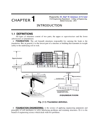
CHAPT ER1 Prepared by: Dr. Rafi' M. Sulaiman Al-Ne'aimi Civil Engineering Department – College of Engineering Duhok University - 2014 INT RODUCT ION 1.1 DEFINITIONS All types of structures consist of two parts; the upper or superstructure and the lower substructure or (foundation). • FOUNDATION:The soil beneath structures responsible for carrying the loads is the foundation. But, in general, it is the lowest part of a structure or building that transmits its weight safely to the underlying soil or rock. Superstructure Substructure T Fig. (1.1): Foundation definition. FOUNDATION ENGINEERING:is the science of applying engineering judgments and principles of soil mechanics to solve interfacing problems and retaining structures. Or it is the branch of engineering science which deals with two problems: •
Foundation Engineering Chapter 1: Introduction 1. Evaluate the ability of soil to carry a load without shear failure or excessive settlement. 2. To design a proper structural member which can transmit the load from superstructure to soil taking economics into consideration. 1.2 CLASSIFICATION OF FOUNDATIONS Foundations can be classified basically into two types:shallow and deep. • Shallow Foundations: These types of foundations are so called because they are placed at a shallow depth (relative to their dimensions) beneath the soil surface. Their depth may range from the top of soil surface to about 3 times the breadth (about 6 meters). They include spreadfootings as circular or square or rectangular in plan which support columns, and strip footings which support walls and other similar structures. In addition to, combined and mat foundations and soil retaining structures (retaining walls, sheet piles, excavations and reinforced earth). •Deep Foundations: The most common of these types of foundations are piles and drilled shafts. They are called deep because they are embedded very deep (relative to their dimensions) into the soil. Their depths may run over several tens of meters. They are usually used when the top soil layers have low bearing capacities (the soil located immediately below the structure is weak, therefore the load of the structure must be transmitted to a greater depth). The shallow foundation shown in Fig. (1.2) has a width B and a length L. The depth of embedment below the ground surface is equal to Df. This depth must be adequate to avoid: 1. Lateral expulsion of soil beneath the foundation. 2. Seasonal volume changes such as freezing or the zone of active organic materials. 3. The depth be sufficient enough that the foundation should be safe against overturning, sliding, rotational failure, and overall soil shear failure and excessive settlement. Theoretically, when B/Lis equal to zero (that is, L = ∞ ), a plane strain case will exist in the soil mass supporting the foundation. For most practical cases when B/L (1/5 to 1/6), the plane strain theories will yield fairly good results. B Load / meter length Ground surface L Df Fig. (1.2): Individual footing. 2
Foundation Engineering Chapter 1: Introduction Terzaghi defined a shallow foundation as one in which the depth, to the width B ( B / Df ≤1). Otherwise, it is considered as deep foundation. In some cases, there is a different depth of embedment below the ground surface on both sides of a foundation as shown in Fig. (1.3). For those cases, side, in addition to, the overburden pressure must be compared with soil cohesion to decide the type of footing required for design as follows: qu ……….. Design the member as a retaining wall. D , is less than or equal f D should be thedepth at shallow f ∑P G.S. G.S. D f 1 D f 2 B Fig. (1.3): Depth of embedment. γ − γ ( D . D . ) If > f f 1 2 2 qu γ − γ ≤ ( D . D . ) If …………Design the member as a footing. f f 1 2 2 q is unconfined compressive strength of soil. where u 2 σ = σ + φ + + φ From soil mechanics principles For Unconfined Compressive Strength Test (U.C.T.): •For Pure Cohesive Soil ( u= φ •For φ − C Soil: . tan ( 45 ) 2 / σ . c . 2 q tan .( 45 σ ) 2 / 0 ; Therefore: 1 3 = 3= and 1 u q = q u ): . 0 C . 2 C . 2 u u = + φ tan .( 45 ) 2 / u (τ ) a- Pure Cohesive Soil q u = = φ = S C , 0 u u 2 C u (σ ) σ 3= σ = 0 q 1 u (τ ) − φ c b- Soil = + σ φ S C . tan u θ C 2 u (σ ) σ = σ 3= q 0 1 u Fig. (1.4): Unconfined compressive strength test. 3
Foundation Engineering Chapter 1: Introduction 1.3 SETTLEMENT AT ULTIMATE LOAD Settlement means a vertical displacement of a structure or footing or road,…etc.. The settlement of the foundation at ultimate load, u S , is quite variable and depends on several factors. Based on laboratory and field test results, the approximate ranges for u below. Soil / Df Sand 0 Sand Large Clay 0 Clay Large For any foundation, one must ensure that the load per unit area of foundation does not exceed a limiting value, thereby causing shear failure in soil. This limiting value is the ultimate bearing capacity, . ult q andgenerally using a factor of safety of 3 to 4 the allowable bearing capacity, . all q can be calculated as: q q . …….………………………….…..……….………………..(1.1) S values of soils are given (%) Su / B B 5 to 12 25 to 28 4 to 8 15 to 20 ult . all= S . F However, based on limiting settlement conditions, there are other factors which must be taken into account in deriving the allowable bearing capacity. The total settlement, T will be the sum of three components: 1. Elastic or immediate settlement, i S ; (major in sand), 2. Primary and Secondary consolidation settlements, c S = i S + c S +cs S …..…………………………..……………………..(1.2) Most building codes provide an allowable settlement limit for a foundation which may be well below the settlement derived corresponding to capacity corresponding to the allowable settlement must also be taken into consideration. A given structure with several shallow foundations may undergo two types of settlement: 1. Uniform or equal total settlement, and 2. Differential settlement. Fig. (1.5a) shows a uniform settlement which occurs when a structure is built over rigid structural mat. However, depending on the load of various foundation components, a structure may experience differential settlement. A foundation may also undergo uniform tilt (Fig. 1.5b) or non-uniform settlement (Fig. 1.5c). In these cases, the angular distortion, Δ, can be defined as: S S (min) t (max) t ′ S S ′ Limits for allowable differential settlement of various structures are available in building codes. Thus, the final design of a foundation depends on: (a) the ultimate bearing capacity, (b) the allowable settlement, and (c) the allowable differential settlement for the structure. S , of a foundation Sandcs S ; (major in clay). T q given by Eq. (1.1). Thus, the bearing all . − Δ = (for uniform tilt)…….....…………………..(1.3) L − t t (max) (min) Δ = (for non-uniform settlement) ……….………..(1.4) L 1 4
Foundation Engineering Chapter 1: Introduction Example (1.1): A 30 cm x 30 cm column is loaded with40 Ton. Check whether the column can be placed on soil directly or not if the allowable bearing capacity of soil is: (a) . all q (b) . all q Solution: Q q . L′ L′ 2 1 L′ L′ G.S. G.S. G.S. t S t S (min .) (min .) St t S St (max .) t S (max .) (a) Uniform settlement (b) Uniform tilt (c) Non-uniform settlement Fig. (1.5): Settlement of a structure. = 50 kg/cm2, and = 1.0 kg/cm2. all= (a) A 40000 cm2 (minimum required area) < 900 cm2 (area of column)………O.K. = = A 800 or 50 40000 = kg/cm2 < 50 kg/cm2……O.K. = q 44 4 . or all . 30 x 30 ∴ No failure may happen; and the column can be placed directly on the soil. 40000 cm2 (minimum required area) > 900cm2 (area of column)..... N.O.K. = = (b) A 40000 0 . 1 ∴ (Not safe) and the column in this case cannot be placed directly on soil, therefore, an enlarged base is required. A = 40000 cm2 = 4 m2 , assuming square area: B = = √4 = 2m. (see Fig. (1.6)). A 40 Ton 40 Ton 2m 30 cm x 30 cm 2m 2 2 qall = (a) . 50 kg . / cm qall = (b) . . 0 . 1 kg / cm Fig. (1.6): Solution of example (1.1). 5
Foundation Engineering Chapter 1: Introduction 1.4 TYPES OF FAILURE IN FOOTINGS It is possible due to load that a footing fails by one or two of the following: (1) Shear failure:this failure must be checked against:- (i) punching shear and (ii) wide beam shear. No shear failure is satisfied by providing an adequate thickness of concrete (see Fig. 1.7). (2) Tension failure: this failure decides the locations and positions of steel distribution. No tension failure is satisfied by providing an adequate steel reinforcement (see Fig. 1.7). 1.5 TYPES OF FOOTINGS (1) Spread or Isolated or Individual Column Footing: It is a footing of plain or reinforced concrete that supports a single column. It may be either a square or circular or rectangular in shape or cross sectional area (see Fig. 1.8). However, the design of square or circular spread footings is simpler than that of rectangular one. This is evident due to the twice calculation required for rectangular footing compared with other ones. The rectangular footing is preferred in case of a moment, since the length is increased in the direction of moment to make the resultant of loads within the middle third of footing. Square footing Circular footing L′ L′ Edge of footing Edge of footing Edge of footing d/2 d/2 d/2 L′ ′ d/2 d/2 d/2 L′ ′ L′ ′ d/2 d/2 L′ d/2 (c) Internal column: = (a) External column: ′ = (b) Corner column: + ′ = ′ ′ ′ + bo ( 2 L L ) ′ ′ + ′ ′ bo 2 L L bo L L (i) Punching shear at (d/2) from face of column. Centerline M M d u u d q d ult . (ii) Wide beam shear at (d) from face of column. (iii) Bending moment. Fig. (1.7): Types of failure in footing. B B B L B = A Rectangular footing Fig. (1.8): Spread footing. 6
Foundation Engineering Chapter 1: Introduction (2) Combined Footing (reinforced concrete only): It is a footing that connects several columns and can take one of the following shapes: •Rectangular Combined Footing (see Fig. 1.9): (a) Used along the walls of building at property lines where the footing for a wall column can not extend outside the limits of the structure. (b) If the loads from several columns are transmitted to the same footing, the footing should be proportioned so that its centroid coincides with the center of gravity of the column loads. •Trapezoidal Combined Footing (see Fig. 1.10): (a)If the maximum load exists at the exterior column, (b)It is not possible to make the resultant of loads passes through the centroid of the footing. L > x > 3 •Strap or Cantilever Combined Footing (see Fig. 1.11): (a) If there is an eccentricity, and/ or L). S Col. 1: 0.4 m x 0.4 m 800 kN 1200 kN Property line 0.3m x 0.3m 0.4m x 0.4m 0.5m Soil pressure 1.3m 4.0m 0.5m Col. 2 Col. 1 Fig. (1.9: Rectangular combined footing. L). (i.e., If 2 (b) If (x < 3 Col. 2: 0.4 m x 0.4 m DL= 385 kN LL= 270 kN Pu1 DL= 190 kN LL= 300 kN Pu2 5.5 m c. g. b a 0.15 m d x strap d footing Property line x′ e = 0.65 m Resultant L Resultant Fig. (1.10): Trapezoidal combined footing. Fig. (1.11): Strap combined footing. 7
Foundation Engineering Chapter 1: Introduction (3) Wall or Strip Footing(plain or reinforced concrete only)(see Fig. 1.12): This footing represents a plain strain condition, such as a footing beneath a wall. In this case, Total load .. / unit length .. = = Area 1 . x . B the footing area is calculated as: q all . (4) Raft Foundation (see Fig. 1.13): Is a combined footing that covers the entire area beneath a structure and supports all the Q= Q = 200 kN/m Q / meter length Sand 0.75m D f W.T. c′ = 0 , Wall footing φ ′ Wall footing = ° 30 = 18 kN/m3 γ 1.5m B m ω=10%, Gs= 2.65 Fig. (1.12): Wall footing. ∑ q walls and columns, such that: < q applied all . A It is used when: •All spread footings areas represent greater than 50 % of the entire site area, •If there is a basement and ground water table problems, •The bearing capacity of soil is very low, and the building loads are so heavy, and •A large differential settlement is expected to occur. y′ I G B C A 0.25 m 400 kN 500 kN 450 kN 7 m 1500 kN 1200 kN 1500 kN 4.25 m 8 m 4.25 m x′ 7 m 1200 kN 1500 kN 1500 kN 7 m 350 kN 500 kN 400 kN 0.25 m E F J H D 8 m 8 m 0.25 m 0.25 m Fig. (1.13): Raft foundation. 8
Foundation Engineering Chapter 1: Introduction (5) Pile Foundation (see Fig. 1.14): Pile is a structural member made of wood, steel or concrete used to transmit the load from superstructure to underlying soil stratum in the following cases: • When the soil profile consists of weak compressible soils, • If . all applied q .. .. q > , • To resist tension or uplift forces induced by horizontal forces acting on superstructure due to wind or earthquakes loads. Piles usually are of two types: (a)Driven piles, suitable for granular soils, (b)Bored piles, suitable for clayey soils, Each type of these piles can be made of precast concrete or cast in place. (6) Pier Foundation (see Fig. 1.15): It is an underground structural member that serves the same purpose as a footing. However, the ratio of the depth of foundation to the base width of piers is usually greater than 4 (Df /B >4), whereas, for footings this ratio is commonly less than unity (Df /B ≤1). A drilled pier is a cylindrical column that has essentially the same function as piles. The drilled pier foundation is used to transfer the structural load from the upper unstable soils to the lower firm stratum. Total load Total load, Q Pile Cap G.S. L G.S. Skin friction, Qs n Piles S S Hard stratum b m Piles End bearing, Qb (a) Single Pile a (b) Layout of Piles in groups. Fig. (1.14): Single and group piles. 9
Foundatio n Engineering g Chap pter 1: Introd duction A part of t on is known a pier shaft atum or it m pier shaft lo and subjec is known as entially, pie rpose. The d hod of ins by driving In general, a the same by group of p the pier a n as a pier may rest dir may be sup ocated at th ted to lat an abutmen ers and piles distinction i stallation. A and a pier a single pier heavy col piles. above the shaft. The rectly on a pported on he end of a teral earth nt. s serve the s based on A pile is r by auger r is used to lumn load foundatio base of a firm stra piles. A bridge a pressure Ess same pur the meth installed drilling. I support resisted b Fig. (1.15 5): Pier foun ndations. (7) Float ting Foun he weight o d soil a foun it is conside dation: of the constr ndation is kn ered as semi If th ructed struct nown as fully -compensate ture or build y compensat ed foundatio ding equal t ed foundatio on. o the weigh on. But if thi ht of the rep is condition placed is not excavated satisfied, (8) Reta aining Wall taining walls lopes. In ge e in the ele ly supported e abutments e many type ents. They're s: s are structu eneral, they evation of th d by soil (or and where es of retaini e mainly cla Ret ures used to are used to he ground s rock) under water may ing walls, e assified accor provide stab o support so surface on e rlying the ba undercut th ach type se rding to its b bility for ear oil banks an each of wal ase slab, or s he base soil rves differe behavior aga rth or other nd water or ll sides. Ret supported on as in water nt purposes ainst the soil materials at also to mai taining wall n piles; as in r front struc and fit diff l as: t their intain ls are n case tures. ferent natural s differenc commonl of bridge There are requirem (a)Grav most const (b)Semi reinf (c)Canti heigh desig indiv (d)Coun howe the w econ (e)Butt braci ng Walls are own weigh not economic etaining Wa are introduc ning Walls It derives it ntilever beam (see Fig. 1.1 taining Wal ave thin vert base slab to n the wall he ining Walls nt of the wal e constructe ht and any cal for walls alls are mod ced. This hel are the mos ts name from ms. The stab 16c). ls are simila tical concrete ogether and eight exceed sthis type i l and is in co ed of plain c soil resting higher than dification of lps minimizi st common t m the fact th bility of this concrete or s on the wal 3m (see Fig f gravity wal ing the wall type of retai hat its indivi s type is a fu stone mason ll for stabili g. 1.16a). ll in which s section (see ining walls t dual parts b unction of th nry. They de ity. This typ epend pe of ity Retainin tly on their truction is n i-Gravity Re forcing steel ilever Retai ht up to 8m. gned as, can vidual parts ( nterfort Ret ever, they ha wall and b nomical when tress Retai ing is in fron small amoun Fig. 1.16b) that used for ehave as, an he strength nts of ). r wall nd are of its ar to cantile e slabs behin reduce the ds 8m (see F is similar to ompression i ever retainin nd the wall k e shear and ig. 1.16d). o counterfor instead of te ng walls, at known as co d bending m regular inte ounterforts th moment. Th rvals, hat tie hey're rt retaining ension. wall, excep pt the 10
Foundation Engineering Chapter 1: Introduction (f) Bridge Abutments are special type of retaining walls, not only containing the approach fill, but serving as a support for the bridge superstructure (see Fig. 1.16f). (g)Crib Walls are built-up members of pieces of precast concrete, metal, or timber and are supported by anchor pieces embedded in the soil for stability (see Fig. 1.16g). Among these walls, only the cantilever retaining walls and bridge abutments are much used. (b) Semi-gravity wall (a) Gravity walls (c) Cantilever wall (d) Counterfort wall (f) Bridge abutment (g) Crib walls Fig. (1.16): Common types of retaining walls. 11
Foundation Engineering Chapter 1: Introduction (9) Sheet Piles Walls: These are classified as; anchored and cantilevered sheet pile walls; each kind of them may be used in single or double sheets walls. (a)Cantilever or Free Sheet-Pile Walls are constructed by driving a sheet pile to a depth sufficient to develop a cantilever beam type reaction to resist the active pressures on the wall. That is, the embedment length which must be adequate to resist both lateral forces as well as a bending moment (see Fig. 1.17a). (b)Anchored or Fixed Sheet-Pile Walls are types of retaining walls found in waterfront construction, which are used to form wharves or piers for loading and unloading ships (see Fig. 1.17b). (10) Caissons: A hollow shaft or box with sharp ends or cutting edges for ease penetrating into soil used to isolate the site of project from the surrounding area. The material inside the caisson is removed by dredged through openings in the top or by hand excavation. Whereas, the lower part of it may be sealed from atmosphere and filled with air under pressure to exclude water from work space (see Fig. 1.18). Fig. (1.18): Methods of caisson construction. s q A A H Anchor tie rod H Dredge line B Dredge line B D D Point of rotation C C (b) Anchored sheet pile wall. (a) Cantilever sheet pile wall. Fig. (1.17): Types of sheet piling walls. (b) T he Gow method. (a) T he Chic ago method. 12
Foundation Engineering Chapter 1: Introduction (11) Cofferdams: (a)Single and Double Sheet Pile Cofferdams: used for depth of water not exceeds 3.0 m. (b)Cellular Cofferdams: used for higher depths of water, i.e., greater than 3.0 m. These are relatively watertight enclosures of wood or steel sheet piles. Before the cofferdam is pumped out, one set of bracing is installed just above the water line. The water level is then lowered to the elevation at which another set of bracing must be installed. Successive lowering of water level and installation of bracing continue until the cofferdam is pumped out (see Fig. 1.19). ° ° 30 30 ° 45 ° 45 (a) Circular, economical for deep cells. (b) Diaphragm, economical in quiet water. (c) Modified circular. Fig. (1.19: Cellular cofferdams. 13