Download
1 / 2
20 likes | 120 Views
UT351 Demonstration Outline. Successful Actions of a Sales Call. Preparation Connect Power Terminals 8,9 & 10 Connect Loop Simulator – 4859SIM - $15.00 Yellow – 12, Red – 13, White – 16, Black – 17 Power on unit If display reads “In” and “OFF”, Power off and begin demo.

E N D
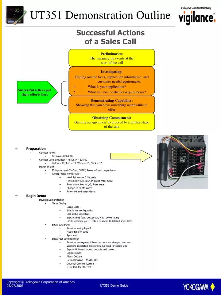
UT351 Demonstration Outline Successful Actions of a Sales Call • Preparation • Connect Power • Terminals 8,9 & 10 • Connect Loop Simulator – 4859SIM - $15.00 • Yellow – 12, Red – 13, White – 16, Black – 17 • Power on unit • If display reads “In” and “OFF”, Power off and begin demo. • Set IN Parameter to “OFF” • Hold Set Key for 3 Seconds • Press arrow key to StUP, press enter twice • Press arrow key to I/O, Press enter. • Change In to off, enter. • Power off and begin demo. • Begin Demo • Physical Demonstration • Show Display • Large LEDs • Simple key configuration • LED status indicators • Explain IP55 face, dust proof, wash down rating • LL100 interface port – Talk a bit about LL100 but show later. • Show data plate • Terminal wiring layout • Model & suffix code • Approvals • Show rear terminal block • Terminal arrangement, terminal numbers stamped on case. • Washers integrated into screws, no need for spade lugs • Explain Universal inputs, outputs and power • Digital Inputs • Alarm Outputs • Retransmission – 15VDC LPS • Optional Communications • RJ45 Jack for Ethernet Preliminaries: The warming up events at the start of the call • Investigating: • Finding out the facts, application information, and customer needs/requirements • What is your application? • What are your controller requirements? Successful sellers put their efforts here Demonstrating Capability: Showing that you have something worthwhile to offer Obtaining Commitment: Gaining an agreement to proceed to a further stage of the sale UT351 Demo Guide
UT351 Demonstration Outline • Set - Up Demonstration • Power up instrument • Explain initial power up screen for simple setup. • Explain short form manuals. • Show the following in the Parameters short form manual • Input range codes table – Set “IN” using this. • Alarm types table • Parameter Setting display (Parameter map) • Set “IN” to 1 & Units to deg F • Scroll through menu briefly talk about units, range setting, RJC & OT. • Set OT = 2 for 4 – 20 ma output. • Exit to main menu – explain that setup for 75% of applications is complete • Show operating display • Scroll between SP and OUT display • A/M key – manual output adjust • Change setpoint to 500 – explain incrementing display speed • Auto Tune • Go to Auto tune parameter, set to “1” • Explain how auto tune bumps process 3 times while tuning occurs • Output changes from 0% to 100% • Process dynamics are observed and PID values are automatically set in controller • Ziegler – Nichols Method used to calculate PID • For more info - “Controller Tuning and Control Loop Performance” by David W. St. Clair • http://members.aol.com/pidcontrol/ to purchase • Increase setpoint 50 deg. and observe overshoot • Explain this is normal PID operation for any controller on the market. • Change setpoint back to 500 deg. • Super Control • Go to SC parameter, set to “1” for overshoot suppression • Explain expert operator • Fuzzy Logic • Setpoint modifier • Learns process • Increase setpoint 50 deg and observe overshoot • Emphasize effect of super control • Set it and forget it • Software Preparation • Ethernet Setup • Set up PC to talk to local IP address • Configure controller to IP address • IP:192.168.1.xxx • Subnet 255.255.255.0 • DG: 0.0.0.0 • ESW 1 • Launch LL100 or LL200 • Software Demo • Explain software tools • Custom Computation Building tool • UT750 & UP750 only • Parameter setting tool • Program pattern setting tool • UP550 & UP750 only • Upload Data from the controller • For Ethernet, set correct address! • Show parameter menus – Explain common parameters applicable to the application • Input/Output parameter setting • Input Type • Output Type • Setup parameters • Alarm Settings • Active color Modes – set to “6” • Zone PID selection • Retransmission Parameters • Digital input selection • Custom select parameters set auto tune parameter • Ethernet • Operating parameter • Alarms • Super Control • Filter and bias • Setpoint Ramps • Output Limits • Active color high and low limits • PID • Show File Information screen • Data is not stored in controller • Save file • Download to controller • Show Tuning screen • Change update time to 1 second • Explain data is instantaneous and not for data acquisition • Change controller modes • Change PID to 5, 240, 60 • Change SP • Wait until controller reaches SP • Run auto tune • Questions? UT351 Demo Guide