Download
1 / 34
370 likes | 821 Views
Chapter 5:Synchronous Sequential Circuits. Logic Design- Review. Logic Circuits. Combinational Circuits. Sequential Circuits. Employ storage elements in addition to logic gates. Outputs are a function of the inputs and the state of the storage elements.

E N D
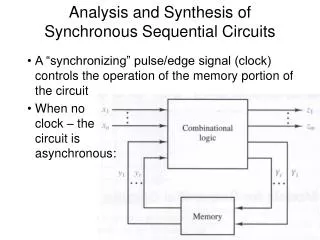
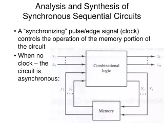
Logic Design- Review Logic Circuits Combinational Circuits Sequential Circuits • Employ storage elements in addition to logic gates. • Outputs are a function of the inputs and the state of the storage elements. • Output depend on present value of input + past input. • Consists of logic gates whose outputs are determined from the current combination of inputs. • Performs an operation that can be specified by a set of Boolean functions.
Overview • Storage Elements and Analysis • Introduction to sequential circuits • Types of sequential circuits • Storage elements • Latches • Flip-flops • Sequential circuit analysis • State tables • State diagrams
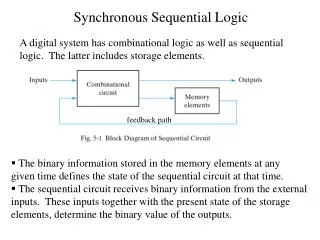
Outputs Inputs Combinational Logic Storage Elements Next State State Introduction to Sequential Circuits • A Sequential circuit contains: • Storage elements:Latches or Flip-Flops • Combinatorial Logic: • Implements a multiple-output switching function • Inputs are signals from the outside. • Outputs are signals to the outside. • Other inputs, State or Present State, are signals from storage elements. • The remaining outputs, Next State are inputs to storage elements.
Outputs Inputs Combina-tional Logic Storage Elements Next State State Introduction to Sequential Circuits • Sequential Logic • Output functionOutputs = g(Inputs, State) • Next state functionNext State = f(Inputs, State)
Types of Sequential Circuits • Depends on the times at which: • storage elements observe their inputs, and • storage elements change their state • Synchronous • Behavior defined from knowledge of its signals at discrete instances of time • Storage elements observe inputs and can change state only in relation to a timing signal (clock pulses from a clock) • Asynchronous • Behavior defined from knowledge of inputs at any instant of time and the order in continuous time in which inputs change • If clock just regarded as another input, all circuits are asynchronous!
X = X 5.3 Storage Elements:Latches • Storage elements • Maintain a binary state (0 or 1) indefinitely as long as power is delivered to the circuit • Switch states (01 or 10) when directed by an input signal • Most basic storage element • Used mainly to construct Flip-Flops • Asynchronous storage circuit • Types of latches: • SR Latches • S`R` Latches • D Latches
R (reset) Q Q S (set) Basic (NOR) S –R Latch • Cross-coupling twoNOR gates gives theS – R Latch:
Q Basic (NAND) S –R Latch S (set) • “Cross-Coupling” two NAND gates gives the S -R Latch: Q R (reset)
S Q C S` Q 1 R 1 R` Clocked S - R Latch • Adding two NANDgates to the basicS - R NAND latchgives the clockedS – R latch: • Has a time sequence behavior similar to the basic S-R latch except that the S and R inputs are only observed when the line C is high. • C means “control” or “clock”.
D Q C Q Q D Q(t+1) Comment 0 0 0 No change D Q 0 1 1 Set Q 1 0 0 Clear Q Q C 1 1 1 No Change D Latch(Transparent Latch) • Adding an inverterto the S-R Latch,gives the D Latch: • Note that there areno “indeterminate”states!
D S Q Q Q Q Q Q C R R Graphic Symbols for latches S D S’R’ SR
Chapter 5: Sequential Circuits 5.4: Flip-Flops
Flip-Flops • The latch timing problem • Master-slave flip-flop • Edge-triggered flip-flop • Other flip-flops - JK flip-flop - T flip-flop
The Latch Timing Problem • In a sequential circuit, paths may exist through combinational logic: • From one storage element to another • From a storage element back to the same storage element • The combinational logic between a latch output and a latch input may be as simple as an interconnect • For a clocked D-latch, the output Q depends on the input D whenever the clock input C has value 1
Y Clock Clock D Q Y Q C The Latch Timing Problem (continued) • Consider the following circuit: • Suppose that initially Y = 0. • As long as C = 1, the value of Y continues to change! • The changes are based on the delay present on the loop through the connection from Y back to Y. • This behavior is clearly unacceptable. • Desired behavior: Y changes only once per clock pulse
The Latch Timing Problem (continued) • A solution to the latch timing problem is to break the closed path from Y to Y within the storage element • The commonly-used, path-breaking solutions replace the clocked D-latch with: • a master-slave flip-flop • an edge-triggered flip-flop
D D D Q Q C C C Master-Slave Flip-Flop Master Slave Y • Consists of two clockedD latches in serieswith the clock on the second latch inverted • The input is observedby the first latch with C = 1 • The output is changed by the second latch with C = 0 • The path from input to output is broken by the difference in clocking values (C = 1 and C = 0). • The behavior demonstrated by the example with D driven by Y given previously is prevented since the clock must change from 1 to 0 before a change in Y based on D can occur.