Download
1 / 31
320 likes | 514 Views
Engine Upper End. Chapter 18. Objectives. Identify all of the parts of the engine's upper end Understand the difference between cylinder head designs Understand the variations in camshaft design Describe different camshaft lobe profiles and their uses

E N D
Engine Upper End Chapter 18
Objectives • Identify all of the parts of the engine's upper end • Understand the difference between cylinder head designs • Understand the variations in camshaft design • Describe different camshaft lobe profiles and their uses • Identify the different cam drive arrangements • Describe the difference between freewheeling and non-freewheeling engines
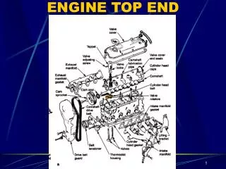
Introduction • Upper end includes: • Cylinder head and heads • Valve train (camshaft and cam drive) • Intake and exhaust manifolds • Covered in another chapter
Cylinder Head Construction • Made of either cast iron or aluminum • Bare head • Head without other parts installed • Other parts • Intake and exhaust valves • Retainers and valve locks • Valve guide seals • Valve springs • Rocker arms
Valve Guides • Tube in cylinder head • Guides valves open and closed • Types: integral and replaceable insert • Integral guides: only used in cast iron cylinder heads • Some iron heads and all aluminum heads have replaceable inserts • Worn valve guides • Affect oil consumption
Valve Guide Seals • Leaking valve guides • Account for nearly half of oil consumption complaints • Valve guide seals are made of several materials • Different resistances to high temperatures • Valve seats • Can be integral or replaceable
Valves • Automotive valves are poppet valves • Intake valves: 35%-40% larger than exhaust valve • Run at high temperatures • Usually made of different materials • Valve stems are often chrome coated • A burned valve will cause misfires • Some heavy-duty engines use sodium-filled valves • Valve stem tip is hardened
Retainers and Keepers • Retainers and valve locks • Hold the spring and valve together • Keepers • Fit into the groove in valve stem • Retainer • Holds spring against spring seat on top of cylinder head • Valve rotators • Cause valve to rotate • Aids in heat removal
Valve Springs • Closes the valve • Some engines have heavier valve springs • Stronger spring tension • Two springs are used • Some springs have a flat wound dampener • Dampens spring vibrations
Pushrods and Rocker Arms • Cam-in-block engines • Use pushrods and rocker arms to transmit motion from the cam lobes to the valves • Rocker arms may have different rocker arm ratios • Some OHC engines use rocker arms
Camshaft • Controls opening and closing of valves • Usually made of hardened cast iron • Cam journals support the camshaft
Number of Cams and Lobes • Depends on number of valves that need to be opened • Usually two cam lobes for each cylinder • Many engines only use one camshaft per cylinder head • Some high-performance engines have four valves per cylinder • Intake and exhaust lobes • Two camshafts for each cylinder • Two lobe types per cylinder
Camshaft Performance • Design determines how well an engine breathes • Production engine: balance between best operation at maximum power and high speed or better fuel economy and low-speed operation • Volumetric efficiency: the more air and fuel drawn into the cylinder in the correct proportion, the more power an engine can produce • Base circle: cam without lobe • Factors of cam lobe profile: duration and valve lift • Mechanical valve lash adjustment: cams have a clearance ramp at lobe beginning and end
Valve Lifters and Lash Adjusters • Lifter: rides on cam lobe • Cam follower: rides on OHC engine lobe • Lifter's convex shape prevents edge loading • OHC engines have hollow camshafts with oil holes
Roller Cam and Lifters • Roller lifter • Cuts valve train friction almost in half • Results in increased horsepower and fuel economy • Roller camshaft • Made of steel • Lobes have a different shape • Allows faster acceleration rates • Valves can be opened faster
Hydraulic Lifters • Eliminate need for periodic valve adjustments, are quiet, and reduce valve train wear • Automatically maintain zero-lash • Construction • Consists of a plunger, plunger return spring, and check valve assembly • Operation • Whenever clearance occurs, a spring between plunger and lifter body causes lifter to expand
Camshaft Drives • Camshaft is driven by the crankshaft by: • Gear drive • Sprockets and timing chain • Sprockets and timing belt • Sprockets and gears • Made of steel, iron, aluminum, or fiber • Timing chains • Roller chain and Morse-type silent chain • Have a drive side and an opposite side where slack accumulates
Camshaft Drives (cont'd.) • Freewheeling engines • Pistons and valves cannot contact each other • Interference engines • Pistons and valves collide • Timing belts • Camshafts on some OHC engines are driven by a timing belt • Several advantaged over chain drives
Valve Timing • Key points • Intake must open before TDC • Stays open longer after BDC • Exhaust valve must open long before end of power stroke • Allowed to remain open past TDC
Valve Timing (cont’d.) • Valve overlap: degrees of crankshaft rotation • Occurs while valves are open at the same time • Most cams are ground with four- to six-degree advance • Better low-end torque • Compensates for timing chain stretch
Variable Valve Timing • Most manufacturers use variable valve timing • Inexpensive way to increase horsepower and control emissions • Variable timing and lift system • Each pair of valves has three cam lobes
Variable Valve Timing (cont'd.) • Variable camshaft phasing • Some VVT systems vary only valve timing but not the lift and duration as described previously • Variable timing and lift plus cam phasing • More complex VVT systems combine VVT and lift with variable camshaft phasing • Atkinson cycle engine • Design used in some hybrid vehicles
Active Fuel Management/Displacement on Demand • Displacement on demand • Means of increasing fuel economy • Engine runs on all of its cylinders when idling • Smooth operation • Valve control using solenoids • Some systems control cam timing using electric solenoid actuators • Directly control valves