Download
1 / 12
130 likes | 236 Views
ATLAS-NSW saclay MMM workshop Mechanical prototypes 4 Modules. Patrick PONSOT & William GAMACHE for the CEA-Saclay-Irfu group:

E N D
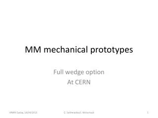
ATLAS-NSWsaclay MMM workshopMechanicalprototypes4 Modules Patrick PONSOT & William GAMACHE for the CEA-Saclay-Irfu group: F.Bauer, P.Daniel-Thomas, E.Ferrer-Ribas, J.Galan, A.Giganon, P-F.Giraud, P.Graffin, S.Hassani, S.Herlant, S.Hervé, F.Jeanneau, H.LeProvost, O.Meunier, A.Peyaud, Ph.Schune 18-19 of April 2013
OUTLINE • MM wedge made of 4 modules (4 quadruplets) • Assembly drawing version E • The drawings of the 4 modules • Global constraints • Do we want to fix also the full size prototype on the spacer-frame? • Design of the spacer-frame • A composite architecture with in-plane corridors included • Not included, but to be considered : 3 double kinematic supports for both MM and sTGC wedges • Design of the modules • A composite architecture • Alignment of 2 dummy PCBs • Gluing of the 4 layers (drift pillars) • Detailed design ? Mesh tension ? • Materials, thickness…etc. • Criteria and measurements to qualify the prototypes • They should be defined before the construction ! Saclay MMM workshop - CEA-Saclay/DSM/Irfu - Patrick PONSOT & William GAMACHE
MM wedge made of 4 modules • The assembly drawing has been updated (version E) • The size of the prototypes has been frozen • The global thickness should not be increased to be able to do the assembly on the spacer • M4 has been simplified by cutting of the ears (rectangular module) Saclay MMM workshop - CEA-Saclay/DSM/Irfu - Patrick PONSOT & William GAMACHE
Modules M1 to M4 • The drawings of the modules have been distributed M3-INFN M1-LMU M4-IRFU (Saclay) M2-USA Saclay MMM workshop - CEA-Saclay/DSM/Irfu - Patrick PONSOT & William GAMACHE
Modules M1 to M4 • Global constraints 1/2 • Remark: For the tooling, don’t forget that we need radial overlap in the future (not included on these prototypes). The size of the module will be changed for the production (2x3 modules?) • A common interface to fix the 3 kinematic mounts on each module has been defined (their position can be exchanged to test the behavior with different orientation of the MM sector) The thickness of the central stiffener has been increased at least to 15mm to fix the interface for kinematic mount and also to have enough space for the electronics M4 M3 At least 20 mm M2 ~80mm M1 2 vertical kinematic mounts per module 1 horizontal kinematic mount Saclay MMM workshop - CEA-Saclay/DSM/Irfu - Patrick PONSOT & William GAMACHE
Modules M1 to M4 • Global constraints 2/2 • Testing of the alignment of 2 dummy PCBs (~450 mm) for each layer ~40 µm • The mesh should be added to take in account the tension ~10-15 N/cm • Flatness of the quadruplet ~50 µm • Parallelism of the 4 layers ~80 µm • Space for electronics and services (see figure below) • Do we want to fix also the full size prototype on the spacer-frame? If not, we need a dummy wedge to complete the sector (symmetrical loading should be tested) ~60mm M4 ~80mm ~150mm Local supports Saclay MMM workshop - CEA-Saclay/DSM/Irfu - Patrick PONSOT & William GAMACHE
Design of the spacer-frame • A composite architecture with in-plane corridors included (if necessary) • Spacer = Central plates = aluminum honeycomb + 2 G10 laminates 1mm • Frame = aluminum profiles • If we need it (see alignment talks), discontinuous central plate to provide space for alignment corridors (3 per module) Local supports for kinematic mounts 12 central plates Holes for alignment corridors 2 aluminum profiles Saclay MMM workshop - CEA-Saclay/DSM/Irfu - Patrick PONSOT & William GAMACHE
Interfaces for sTGc wedges • Not included, but to be considered : 3 double kinematic supports for both MM and sTGC wedges • The weight of the sTGC wedges will not induced deformation of the MM spacer: Direct transfer to the structure of the wheel Saclay MMM workshop - CEA-Saclay/DSM/Irfu - Patrick PONSOT & William GAMACHE
Design of the module • The quadruplets are made of PCBs (0.5mm), G10 skins (0.5mm) and honeycombs (~10mm)… • Estimation of the weight of the MM part is ~440Kgs, but it depends of materials used for the frames and honeycombs (aluminum, G10, Paper…) • Spacer, electronics, services are not included M4 M3 M2 M1 Saclay MMM workshop - CEA-Saclay/DSM/Irfu - Patrick PONSOT & William GAMACHE
Design of the module • All is open for the internal components of the module (if the global constraints are taken in account) • Acomposite architecture: 0.5mm skins + honeycombs 10mm + frames • At least 15mm for the central stiffener to create enough space for electronics • Global thickness of the quadruplet should not exceed 80mm • Alignment of 2 dummy PCBs to form the skin: optical or mechanical methods • Gluing or screwing of the 4 layers? Drift pillars (spacers) are needed to guaranty the same deformation of the 4 layers (in-plane alignment is only outside) • Fixation of the frame to apply the Mesh tension (fixed on the drift stiffener) • Detailed design should be defined according to your assembly procedure • Material for modules: aluminum, paper, G10, FR4 can be used if we respect the symmetry and the planarity of the structures (simulations are ok) • ..etc. Saclay MMM workshop - CEA-Saclay/DSM/Irfu - Patrick PONSOT & William GAMACHE
Qualification of M1 to M4 • Criteria and measurements to qualify the mechanical prototypes • Alignment of 2 dummy PCBs (~450 mm) for each layer and alignment of the 4 layers (resolution ~40 µm) • Measurements on a CMM machine? • Some “targets” should be add on the dummy PCBs. They must be accessible for measurement after assembly • Flatness of the quadruplet ~50 µm and parallelism of the 4 layers ~80 µm • Measurement during the construction on the granite table, on a CMM • Measurement of the 2 external sides after construction • Geometry of the quadruplet within a temperature gradient • Measurement on a CMM machine? • Warming ofone side of the quadruplet (ΔT 2°C)? • Geometry of the assembly of the MM sector (flatness of the external sides and positioning of the modules) • Measurement on a CMM machine? Where (2.8mx2.3mx0.2m)? • CMM at Freiburg: L-l-h = 6.5mx1.5mx1.2m • Some “targets” should be present on each module Saclay MMM workshop - CEA-Saclay/DSM/Irfu - Patrick PONSOT & William GAMACHE
Thank you for your attention ! Commissariat à l’énergie atomique et aux énergies alternatives Centre de Saclay| 91191 Gif-sur-Yvette Cedex T. +33 (0)1 69 08 79 30 | F. +33 (0)1 69 08 89 47 Etablissement public à caractère industriel et commercial | RCS Paris B 775 685 019 DSM IrfuSIS/LCAP (PC N°12, Bt 123)Patrick PONSOT Saclay MMM workshop - CEA-Saclay/DSM/Irfu - Patrick PONSOT & William GAMACHE