Download
1 / 24
240 likes | 358 Views
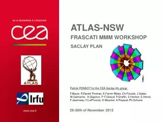
ATLAS-NSW SACLAY MMM workshop Simulations of the mm wedges with the layout option #3B. Patrick PONSOT & Patrick GRAFFIN for the CEA-Saclay-Irfu group:

E N D
ATLAS-NSWSACLAY MMM workshopSimulations of the mm wedges with the layout option #3B Patrick PONSOT & Patrick GRAFFIN for the CEA-Saclay-Irfu group: F.Bauer, P.Daniel-Thomas, E.Ferrer-Ribas, J.Galan, W.Gamache, A.Giganon, P-F.Giraud, S.Hassani, S.Herlant, S.Hervé, F.Jeanneau, H.LeProvost, O.Meunier, A.Peyaud, Ph.Schune 18-19 of April 2013
OUTLINE • Evolution of the layout • From more than 10 configurations for a sector… • … to the open issue : Can we screwed the MM quadruplets on a spacer? • What are the MM layout options #3A and #3B • Thermo-mechanical simulations with screwing of the MM wedges (option #3B) • Methodology: progressive approach • Exchange of materials for the structures (aluminum vs G10) • Comparison of the results • Conclusion • Impact on the design of the quadruplets? Saclay MMM workshop - CEA-Saclay/DSM/Irfu - Patrick PONSOT & Patrick GRAFFIN
Evolution of the layout 3 configurations are considered : Option #1 – all is glued Option #2 – external frame Option #3 – central spacer More than 10 configurations for a sector ! 3 options to do the assembly of the 4 wedges ! Agreement to build wedges for both sTGC & MM 2 options to build a MM wedge 3rd MMM-Saclay 18-19th of Apr. Special week #11 of Mar. 3 layout meetings 2nd MMM-CERN 21-22nd of Feb. 2013 NSW milestones review 17th of Jan. Results? 1st MMM-Frascati 29-30th of Nov. Option #3: Double kinematic supports to separate sTGC and MM wedges Asking for simulation of the full size MM wedges by screwing them on a spacer Simulations of the wedges made of 2x4 modules, fixed with kinematic supports on a spacer-frame 2 options to build the 2 MM wedges (modules vs full size wedges) 2012 ATLAS upgrade week 21th of Nov Saclay MMM workshop - CEA-Saclay/DSM/Irfu - Patrick PONSOT & Patrick GRAFFIN
MM Layout options #3A and #3B • Layout option #3A (Saclay proposal – Patrick P. and Patrick G.) • The 2 MM wedges are made of 2x4 (or 2x3) modules • The modules are fixed on a spacer frame by using kinematic mounts • Floating quadruplets, no external constraints • Layout option #3B (CERN proposal – Joerg W. and Givi) • Full size MM wedges, the 2 MM wedges are screwed on an aluminum spacer • Screwed quadruplets, external constraints must be taken in account (friction factor, tear forces of the screws) Saclay MMM workshop - CEA-Saclay/DSM/Irfu - Patrick PONSOT & Patrick GRAFFIN
THERMO-MECHANICAL Simulations • Thermo-mechanical simulations with screwing of the MM wedges (option #3B) Preliminary remark, valid for all the talks done by the Saclay NSW team: In all cases the thermo-mechanical simulations are made with simplified modelling*. The results must be considered as predictive tendencies and not as absolute values. * The detailed design of the structures is not defined * The tension of the mesh is not included (simulation in progress) Saclay MMM workshop - CEA-Saclay/DSM/Irfu - Patrick PONSOT & Patrick GRAFFIN
THERMO-MECHANICAL Simulations • Methodology: Progressive approach • Why? The final modelling should take in account the friction factors coupled with the tear force of the screws (FEA with contact elements). No-linear calculation induces very long time consuming. Today we need one night to do the computation with simplified model. (geometry, pre-processing, computation and post-processing → only 2 simulations per week) • How? Instead of a lot of tests, we decided to use simplified modelling to reduce the number of simulations • Plan ? for the thermo-mechanical simulations (weight+ temperature gradient 2°C) • Step 1: The MM sector without the screws (all is glued, aluminum excepted for the skins) • Step 2: Full size wedges with aluminum, only screwed on the external frame of the spacer • Step 3: Full size wedges with G10, only screwed on the external frame of the spacer • Step 4 (a consequence of the result of step 3): 2x3 modules screwed on the external frame of the modules • Step 5: Introduction of the friction factors (no-linear calculation), but before this…maybe a step 4-Bis can be required Saclay MMM workshop - CEA-Saclay/DSM/Irfu - Patrick PONSOT & Patrick GRAFFIN
THERMO-MECHANICAL Simulations • Screwing of the MM wedges (option #3B) • For the composite materials, the mechanical characteristics are fully dependent of their origin (datasheet is needed for all of them) • Material used for the simulations: Saclay MMM workshop - CEA-Saclay/DSM/Irfu - Patrick PONSOT & Patrick GRAFFIN
THERMO-MECHANICAL Simulations • Step 1 to 3: Full size wedges (sector 5) • Geometry, boundary and loading conditions • Full size wedge + spacer • 3 kinematic mounts on the spacer • Self weight, Inclined at 0.704°, temperature gradient in Z direction ΔT=2°C Saclay MMM workshop - CEA-Saclay/DSM/Irfu - Patrick PONSOT & Patrick GRAFFIN
THERMO-MECHANICAL Simulations • Step 1: The MM sector without the screws (all is glued, aluminum except for the skins) • Displacement on IP side ~0.05 mm ~0.02 mm Global 3D < 0.1 mm ~0.1 mm If all is glued, the displacements out of the plane are under 50 microns Saclay MMM workshop - CEA-Saclay/DSM/Irfu - Patrick PONSOT & Patrick GRAFFIN
THERMO-MECHANICAL Simulations • Step 2: Full size wedges with aluminum, only screwed on the external frame of the spacer (no sliding for the screws) • Displacement and stresses for the spacer Global 3D < 0.1 mm ~19 MPa Displacements of the spacer are under 100 microns but the stresses are increased by a factor 10 Saclay MMM workshop - CEA-Saclay/DSM/Irfu - Patrick PONSOT & Patrick GRAFFIN
THERMO-MECHANICAL Simulations • Step 2: Full size wedges with aluminum, only screwed on the external frame of the spacer (no sliding for the screws) • Displacement on IP side and stresses for the wedge ~15 MPa ~0.03 mm (“without the effect of the displacement of the spacer”, friction factor is not included) Global 3D ~0.08 mm Displacements (due to thermal expansion) out of the plane are under 50 microns but the shear stresses are increased by a factor 10 : The gluing of the skins can be broken ! Saclay MMM workshop - CEA-Saclay/DSM/Irfu - Patrick PONSOT & Patrick GRAFFIN
THERMO-MECHANICAL Simulations • Step 3: Full size wedges with G10 and paper honeycomb,only screwed on the external frame of the spacer (no sliding for the screws) • Displacement and stresses for the spacer ~7 MPa Global 3D < 0.15 mm Displacements of the spacer are increased to 0.15mm and will deform the wedges out of the plane. The stresses are increased by a factor 5. Saclay MMM workshop - CEA-Saclay/DSM/Irfu - Patrick PONSOT & Patrick GRAFFIN
THERMO-MECHANICAL Simulations • Step 3: Full size wedges with FR4 and paper honeycomb,only screwed on the external frame of the spacer (no sliding for the screws) • Displacement on IP side and stresses for the wedge ~7 MPa Global 3D ~0.05 mm ~0.02 mm (“without the effect of the displacement of the spacer”, friction factor is not included) Displacements of the spacer are increased to 0.15mm and will deform the wedges out of the plane. The shear stresses are increased by a factor 5. Saclay MMM workshop - CEA-Saclay/DSM/Irfu - Patrick PONSOT & Patrick GRAFFIN
THERMO-MECHANICAL Simulations • Due to the increasing of the shear stresses, it has been decided to study the effect of cutting the wedge (step 4) Saclay MMM workshop - CEA-Saclay/DSM/Irfu - Patrick PONSOT & Patrick GRAFFIN
THERMO-MECHANICAL Simulations • Step 4: Geometry, boundary and loading conditions (sector 5) • 2x3 modules + spacer • 3 kinematic mounts on the spacer • Self weight + Inclined at 0.704° + temperature gradient in Z direction ΔT=2°C Saclay MMM workshop - CEA-Saclay/DSM/Irfu - Patrick PONSOT & Patrick GRAFFIN
THERMO-MECHANICAL Simulations • Step 4: 2x3 modules withaluminum frames and aluminum honeycombs, only screwed on their external frame on an aluminum spacer (FR4 skins 0.5mm) • Displacement for the modules on IP side ~70µm Global 3D ~100µm ~35µm Saclay MMM workshop - CEA-Saclay/DSM/Irfu - Patrick PONSOT & Patrick GRAFFIN
THERMO-MECHANICAL Simulations • Step 4: 2x3 modules withaluminum frames and aluminum honeycombs, only screwed on their external frame on an aluminum spacer (FR4 skins 0.5mm) • Stresses for the modules on IP side Up to ~29 MPa localized on the holes of the frames, but this is not a problem for aluminum material ~2 MPa Saclay MMM workshop - CEA-Saclay/DSM/Irfu - Patrick PONSOT & Patrick GRAFFIN
THERMO-MECHANICAL Simulations • Step 4: 2x3 modules withaluminum frames and aluminum honeycombs, only screwed on their external frame on an aluminum spacer (FR4 skins 0.5mm) • Stresses for the spacer Up to ~21 MPa but this is not a problem for aluminum material Saclay MMM workshop - CEA-Saclay/DSM/Irfu - Patrick PONSOT & Patrick GRAFFIN
THERMO-MECHANICAL Simulations • Step 4: 2x3 modules withG10 frames and paper honeycombs, only screwed on their external frame on a G10 spacer (FR4 skins 0.5mm) • Displacement for the modules on IP side ~50µm Global 3D ~70µm ~18µm Saclay MMM workshop - CEA-Saclay/DSM/Irfu - Patrick PONSOT & Patrick GRAFFIN
THERMO-MECHANICAL Simulations • Step 4: 2x3 modules withG10 frames and paper honeycombs, only screwed on their external frame on a G10 spacer (FR4 skins 0.5mm) • Stresses for the modules on IP side Up to ~9 MPa but localized around the holes Less than ~2MPa for the skins Saclay MMM workshop - CEA-Saclay/DSM/Irfu - Patrick PONSOT & Patrick GRAFFIN
THERMO-MECHANICAL Simulations • Step 4: 2x3 modules withG10 frames and paper honeycombs, only screwed on their external frame on a G10 spacer (FR4 skins 0.5mm) • Stresses for the spacer Up to ~8 MPa but this is not a problem for G10 material Saclay MMM workshop - CEA-Saclay/DSM/Irfu - Patrick PONSOT & Patrick GRAFFIN
THERMO-MECHANICAL Simulations • Comparison of the results from step1 to step 4 Don’t forget that the tension of the mesh is not taken in account (new simulations in progress) Saclay MMM workshop - CEA-Saclay/DSM/Irfu - Patrick PONSOT & Patrick GRAFFIN
THERMO-MECHANICAL Simulations • Conclusion • For the full size wedge, the main issue is the shear stresses induced in the glue film used to fix the skins (up to 15MPa) • In theory, the problem can be solved by cutting the skins and addition of a expandable profile (few microns). A new simulation should be done to check this: Step 4-Bis • If it is needed, can we design a full wedge with a segmentation w.r.t. the width of the PCBs (450mm) • A radial flexible profile should be added between each couple of PCBs or skins, is it realistic ? • The bending of the quadruplets is the result of the thermal expansion. This deformation will be amplified, if we have not full contact with the spacer: The flatness and the symmetry of the quadruplet, after construction and after assembly with the spacer are crucial. ~10mm ~450mm Saclay MMM workshop - CEA-Saclay/DSM/Irfu - Patrick PONSOT & Patrick GRAFFIN
Thank you for your attention ! Commissariat à l’énergie atomique et aux énergies alternatives Centre de Saclay| 91191 Gif-sur-Yvette Cedex T. +33 (0)1 69 08 79 30 | F. +33 (0)1 69 08 89 47 Etablissement public à caractère industriel et commercial | RCS Paris B 775 685 019 DSM IrfuSIS/LCAP (PC N°12, Bt 123)Patrick PONSOT Saclay MMM workshop - CEA-Saclay/DSM/Irfu - Patrick PONSOT & Patrick GRAFFIN