Download
1 / 16
200 likes | 597 Views
MECH3300 Finite Element Methods. Lecture 5 Formulation of approximate stiffness matrices Planar elasticity problems Meshing 2D problems. Strain energy in plane stress.

E N D
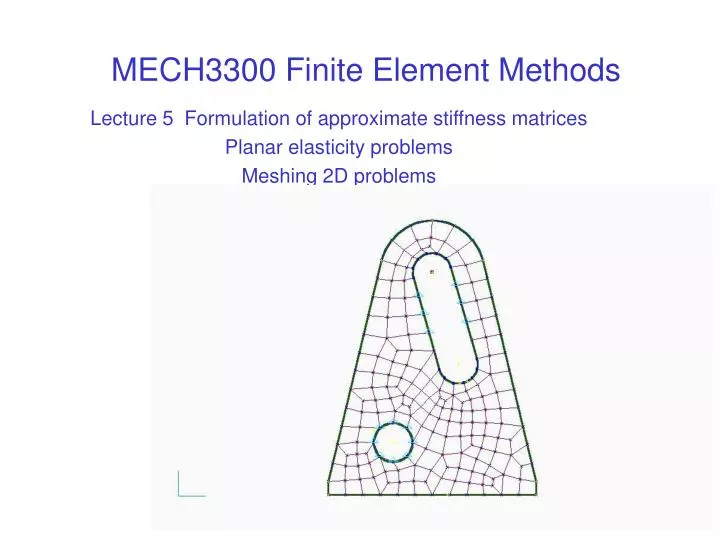
MECH3300 Finite Element Methods Lecture 5 Formulation of approximate stiffness matrices Planar elasticity problems Meshing 2D problems
Strain energy in plane stress • Recall that we can estimate the stiffness of a structural finite element by expressing its strain energy in terms of its nodal displacements. • For uniaxial stress, strain energy per volume is s e /2, the area under an elastic stress-strain curve. • For plane stress in the xy plane, stresses are sx ,sy and txy only. • The strain energy per volume is V = 1/2 (sxex + syey + txygxy) or • Writing stresses and strains as vectors is a notation of convenience - they do not behave as vectors.
Elastic stress-strain relations • For any linear elastic problem we can write a set of linear equations relating stress to strain. The equations change with the type of problem (eg plane stress, plane strain, solid etc.) • For plane stress, writing stress in terms of strain leads to a elasticity matrix [D], where E is Young’s modulus and n is Poisson’s ratio. • s = [D]eor • [D] changes with the analysis type • eg for a solid element [D] is 6 by 6, as there are 3 direct strains and three shear strains at some location in a solid element.
Strain energy in terms of strain • Combining the stress-strain relation with the expression for strain energy and integrating over an element, we get t is element thickness, and A its area. To evaluate this integral, we need strains expressed in terms of nodal displacements - this is done with the interpolation functions. Now, recall for the linear interpolation triangle that x-displacement anywhere in the element is u(x,y) = N1(x,y) u1 + N2(x,y) u2 + N3(x,y) u3 The x-strain is There are similar expressions for y-strain and shear strain. Collectively the strains, written in a column vector, are e = B u, the terms of the matrix B being either zero or derivatives of interpolation functions like those above.
Strain energy of an element and its stiffness matrix • The transpose of e = B u is eT = uTBT • Substituting in • gives • Hence the element stiffness matrix can be written as • This integral is normally found numerically, as a weighted sum of the integrand evaluated at integration points (called Gauss points) within the element. The terms of B are constant for the 3 node triangle, but are in general functions of position. The number of rows of B varies with the number of strain components that are relevant. The number of columns of B depends on the number of nodal degrees of freedom that the element has.
Common types of 2D elasticity problems • Most packages given the user the choice of plane stress, plane strain or axisymmetric analysis with 2D “planar elasticity” elements. • Plane stress occurs on an free surface or in a thin plate loaded in-plane. • A plane stress analysis can also be used to analyze a detail like a stress concentration. • One example is a plate containing a regular grid of holes. We do not wish to model all the holes, as that would require a very fine mesh. An alternative is to mesh a small region of plate containing one hole with plane stress elements and estimate effective values of E and n, from its deformation under load. Question: how to load and restrain this?
Plane strain problems • Plane strain strictly refers to no movement at all in the 3rd dimension. This is an ideal which is approached in certain cases, where Poisson’s ratio effects tend to be prevented. • A classic example is the tip of a crack in a thick plate. The surrounding material away from the crack tip is less stressed and resists the large Poisson ratio contraction that would otherwise occur in the direction along the crack tip, due to the high stresses at the crack tip. Hence a situation of plane strain develops at the crack tip, except at the ends. Contraction prevented in this direction Mesh (portion) Load Plane strain is often assumed when modelling a typical cross-section through something long in the 3rd dimension.
Axisymmetric problems • The most common type of 2D problem - model a half-section containing the axis, with each element representing a complete ring of material. • If the loading is radial and axial only, and does not vary with angle circumferentially (eg inertia of a spinning disk), then the deformation is in the plane modeled. z Packages usually assume that x = radius x Region modeled Actual object
Stresses and strains in planar elasticity • For plane stress, there are in-plane stresses sxsytxyonly. There is out-of-plane direct strain ez • For plane strain there is no out-of-plane strain, but there is out-of-plane stress sz • In an axisymmetric problem, there is out-of-plane stress and strain called hoop stress and strain. • Hoop strain = change in circumference/circumference = Dr/r • Hence there is no rigid body displacement radially, and rigid body motion can be prevented by stopping an axial displacement.
Combined stresses • While the state of stress at a point is represented by 3 principal stresses, these can also be combined to get other measures of stress. • For isotropic materials, 2 stresses to compare to yield are commonly used • Tresca stress - the diameter of the largest of 3 Mohr’s circles or twice the maximum shear stress in a principal plane. • Von Mises stress - a value proportional to the square root of energy of distortion, that part of strain energy causing change of shape, as opposed to volume change. t s sTr For plane stress
Compatibility in meshing • Compatibility means that things fit together when deformed. • With finite elements this means displacements agree between neighbouring elements, not only at the nodes, but all along common edges in 2D or all over common surfaces in 3D. • This means that one element can only join one other element, not 2 to 1 or 3 to 1. This node is not connected to the top element, as it has no mid-side node. Hence it can move up and down independently and we have a model of a crack. This is incompatible.
Transition meshes • To change mesh refinement between two regular grids, transition meshes are needed. eg Packages permit the user to replace an element with grading subdivisions like these.
Element distortion and the patch test • Distorted elements are less accurate,especially as 2 sides come close to being parallel. In automatic meshing, a tolerance is set on element distortion. • A test of how well elements cope with distortion is the patch test. A group of distorted elements are loaded in a way that should produce uniform stress, and the actual stress in the elements is examined to see if it is uniform. eg P P
Interpolation in natural coordinates • Interpolation over a quadrilateral or hexahedral element can be described most neatly using non-Cartesian axes that bisect the sides of the element. • In 2D, coordinates r and s that range from -1 to 1 across the element are used. • Interpolation of x-displacement is • u = 1/4 (1+r)(1+s) u1 +1/4(1-r)(1+s) u2 + 1/4 (1-r)(1-s) u3 + 1/4 (1+r)(1-s) u4 • ie u = u1at r = s = 1 etc s 1 2 1 r 1 -1 4 -1 3
Limits to distortion of quadrilateral elements • Strains found in r, scoordinates need to be transformed to give strains in global x, y coordinates when estimating strain energy and hence stiffness. • This transformation can fail if 2 element sides are parallel or if a corner angle exceeds 90 degrees. Unacceptable quadrilateral elements
Interpolation on a triangle • The neatest way to write the interpolation functions for a triangular 2D element is to make them functions of area coordinates. • An area coordinate is the fraction of the area occupied by a subtriangle, with its apex at the point of interest. • For a 3 node triangle, the interpolation of x-displacement is simply • u = S1 u1 + S2 u2 + S3 u3 • Note at node 1, S1 = 1. At node 2 or 3, S1 = 0 so it works as an interpolation function. 3 S1= A1/A S2 = A2/A S3 = A3/A A1 A2 As S1 + S2 + S3 = 1 only 2 of these are independent coordinates. 1 2 A3