Download
1 / 68
740 likes | 1.05k Views
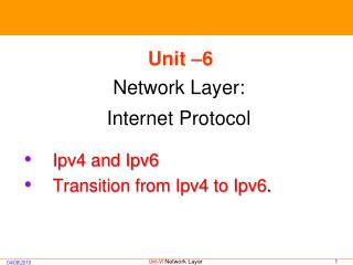
Unit –6 Network Layer: Internet Protocol. Ipv4 and Ipv6 Transition from Ipv4 to Ipv6. Network Layer. Physical and data link layers of a network operate locally. In the Internet model, the main network protocol is the Internet Protocol (IP)

E N D
Unit –6 Network Layer: Internet Protocol • Ipv4 and Ipv6 • Transition from Ipv4 to Ipv6.
Network Layer • Physical and data link layers of a network operate locally. • In the Internet model, the main network protocol is the Internet Protocol (IP) • Concerned with getting packets from source to destination. • The network layer must know the topology of the subnet and choose appropriate paths through it. • When source and destination are in different networks, the network layer (IP) must deal with these differences.
IP is the highest layer protocol which is implemented at both routers and hosts
IP Service • IP provides an unreliable connectionless best effort service (also called: “datagram service”). • Unreliable: IP does not make an attempt to recover lost packets • Connectionless:Each packet (“datagram”) is handled independently. IP is not aware that packets between hosts may be sent in a logical sequence • Best effort: IP does not make guarantees on the service (no throughput guarantee, no delay guarantee,…) • Consequences: • Higher layer protocols have to deal with losses or with duplicate packets • Packets may be delivered out-of-sequence
IP Service unicast broadcast multicast • IP supports the following services: • one-to-one (unicast) • one-to-all (broadcast) • one-to-several (multicast) • IP multicast also supports a many-to-many service. • IP multicast requires support of other protocols (IGMP, multicast routing)
INTERNETWORKING In this section, we discuss internetworking, connecting networks together to make an internetwork or an internet. Need for Network LayerInternet as a Datagram NetworkInternet as a Connectionless Network
Links between two hosts • 5 networks, 4 LANs and 1 WAN. • A->S1->S3->D, Physical and Data Link layer are involved. • Data link and Physical link layer does not have the routing information.
Links between two hosts • Need for Network Layer • When data arrives at interface f1 of Router 1(R1), how does R1 know that interface f3 is the outgoing interface ? • There is no provision in the data link layer to help R1 make the decision. • The frame does not carry any routing information. • The frame contains the MAC address of A as the source address and MAC address of R1 as the destination address. • Solution: • To solve this problem the network layer was designed. • The network is responsible for host-to-host delivery and for routing the packets through the routers or switches.
Network layer in an internetwork • Header of the packet contains logical addresses of the source and destination. • Network layer maintains Routing table
Network layer at the source, router, and destination • Network Layer at the source is responsible for creating a packet from the data coming from another protocol. • The header of the packet contains, among other information , the logical addresses of the source and destination. • Network Layer is responsible for checking its routing table to find the routing information . • Network Layer at the destination is responsible for address verification
Network layer at the source, router, and destination • Network Layer at the router is responsible for routing the packets. • Router or switch consults its routing table and finds the interface from which the packet must be sent.
Switching Techniques • Three types of switching techniques: • Circuit Switching • Packet Switching • Message Switching (a) Circuit switching. (b) Packet switching.
Circuit Switching • Dedicated communication path between two stations • Three phases • Establish • Transfer • Disconnect • Must have switching capacity and channel capacity to establish connection • Must have intelligence to work out routing • Inefficient • Channel capacity dedicated for duration of connection • If no data, capacity wasted • Set up (connection) takes time • Once connected, transfer is transparent • Developed for voice traffic (phone)
Public Circuit Switched Network • Circuit switching designed for voice • Resources dedicated to a particular call • Much of the time a data connection is idle • Data rate is fixed • Both ends must operate at the same rate
Packet Switching Principles Basic Operation • Data transmitted in small packets • Typically 1000 octets • Longer messages split into series of packets • Each packet contains a portion of user data plus some control info • Control info • Routing (addressing) info • Packets are received, stored briefly (buffered) and past on to the next node • Store and forward
Packet Switching Technique • Station breaks long message into packets • Packets sent one at a time to the network • Packets handled in two ways • Datagram • Virtual circuit
Datagram • Each packet treated independently • Packets can take any practical route • Packets may arrive out of order • Packets may go missing • Up to receiver to re-order packets and recover from missing packets
Internet as Datagram Network Internet as Datagram Network • The internet is packet switched network and uses datagram approach to switching in the network layer. • Uses universal addresses defined in the network layer to route packets from the source to destination.
Internet as a Connectionless Network Connection-oriented Protocols • A setup stage is used to determine the end-to-end path before a connection is established. • Data flow streams are identified by some type of connection indicator • Packets are sent on the same path in sequential order. • Connection is terminated when all the packets are delivered Connectionless Protocols • No set up is needed. • Each packet contains information which allows the packet to be individually routed hop-by-hop through the network. • Packets may or may not have travel the same path to the destination. • Internet used this type of service because it is impossible to connection from source to destination
Connection-Oriented Concatenation of Virtual Circuits Internetworking using concatenated virtual circuits.
Connectionless Internetworking A connectionless internet.
Switching at the network layer in the Internet uses the datagram approach to packet switching. Communication at the network layer in the Internet is connectionless.
IPv4 The Internet Protocol version 4 (IPv4) is the delivery mechanism used by the TCP/IP protocols. IPv4: Connectionless Datagram protocol Best effort protocol and does not provides error and flow control (error detection on the header) DatagramFragmentationChecksum Options
Datagram Datagram • Packets in the IPv4 layer are called datagrams.
IPv4 datagram format • Packets in the IPv4 layer are called datagrams. • Consists of Header and Data
VER HLEN Service Total Length Flags Fragment Offset TTL Protocol Header Checksum Source/Destination IP Addresses Options • Version (VER): is the field that contains the IP protocol version. The current version is 4. 5 is an experimental version. 6 is the version for IPv6. • Header Length (HLEN): is the length of the IP header in multiples of 32 bits, without the data field. • The minimum value for a correct header is 5 (i.e., 20 bytes), the maximum value is 15 (i.e., 60 bytes).
VER HLEN Service Total Length Flags Fragment Offset TTL Protocol Header Checksum Source/Destination IP Addresses Options • Service Type: (8 bit) is an indication of the quality of service requested for this IP datagram. It contains the following information. • Precedence: ( first 3 bits) specifies the nature/priority: of the datagaram in issues such as congestion. • 000: Routine 001: Priority 010: Immediate 011: Flash 100: Flash override 101: Critical 110: Internetwork control 111: Network control • The next 4 bits are called type of service (TOS) bits,
VER HLEN Service Total Length Flags Fragment Offset TTL Protocol Header Checksum Source/Destination IP Addresses Options • The last bit is reserved for future use.
VER HLEN Service Total Length Flags Fragment Offset TTL Protocol Header Checksum Source/Destination IP Addresses Options Values for codepoints • Internet Control Message Protocol: ICMP Internet Group Management Protocol:IGMPTransmission Control Protocol:TCP User Datagram Protocol:UDP Open Shortest Path First:OSPF Bootstrap Protocol: BOOTP, Simple Network Management Protocol:SNMP Interior gateway protocolIGP) Simple Network Management Protocol (SNMP) Trivial File Transfer Protocol (TFTP) Domain Name System (DNS)
VER HLEN Service Total Length Flags Fragment Offset TTL Protocol Header Checksum Source/Destination IP Addresses Options • Total Length: (16 bits) Specifies the total length of the IPv4 datagram, header and data, in octets. 216-1=65,535 bytes. • Length of data = total length – header length • Identification: is a unique number assigned by the sender used with fragmentation. • Flags contains control flags: • – the first bit is reserved and must be zero; • – the 2nd bit is DF (Do not Fragment), 0 means allow fragmentation; – the third is MF (More Fragments), 0 means that this is the last fragment.
VER HLEN Service Total Length Flags Fragment Offset TTL Protocol Header Checksum Source/Destination IP Addresses Options Encapsulation of a small datagram in an Ethernet frame
VER HLEN Service Total Length Flags Fragment Offset TTL Protocol Header Checksum Source/Destination IP Addresses Options • Fragment Offset is used to reassemble the full datagram. The value in this field contains the number of 64-bit segments (header bytes are not counted) contained in earlier fragments. If this is the first (or only) fragment, this field contains a value of zero. • TTL (Time to Live) specifies the time (in seconds) the datagram is allowed to travel. In practice, this is used as a hop counter to detect routing loops.
VER HLEN Service Total Length Flags Fragment Offset TTL Protocol Header Checksum Source/Destination IP Addresses Options • Protocol: 8 bit field indicates the higher level protocol to which IP should deliver the data in this datagram. E.g., ICMP = 1; TCP = 6; UDP = 17. (Internet message control protocol, Internet group management protocolsteam control transmission protocoltransmission control protocoluser datagram protocolopen shortest path first)
VER HLEN Service Total Length Flags Fragment Offset TTL Protocol Header Checksum Source/Destination IP Addresses Options • Header Checksum is a checksum for the information contained in the header. If the header checksum does not match the contents, the datagram is discarded. • Source/Destination IP Addresses are the 32-bit source/destination IP addresses. • Options: The header consists of 2 parts: fixed part and a variable part. Fixed part is of 20 bytes. The maximum size of the Variable part is 40 bytes. Variable-length field (there may be zero or more options) used for network testing and debugging • Padding is used to ensure that the IP header ends on a 32 bit boundary. The padding is zero
Fragmentation Fragmentation
Fragmentation • Process of dividing a datagram is called Fragmentation • IP provides fragmentation/reassembly of datagrams. • The maximum length of an IP datagram is 65,535 bytes. When an IP datagram travels from one host to another, it may pass through different physical networks. • Maximum transfer unit (MTU) • Each physical network has a maximum frame size, called maximum transmission unit (MTU), which limits the datagram length. • A fragment is treated as a normal IP datagram while being transported to their destination. • If one of the fragments gets lost, the complete datagram is considered lost. It is possible that fragments of the same IP datagram reach the destination host via multiple routes. • Finally, Since they may pass through networks with a smaller MTU than the sender’s one, they are subject to further fragmentation.
Maximum transfer unit (MTU) MTUs for some networks Fiber Data Distributed Interface (FDDI) Point-to-Point Protocol (PPP)
Fields Related to Fragmentation • Identification, Flags ,Fragmentation offset Field • At the destination host, data are reassembled into the original datagram. • The identification field set by the sending host is used together with the source and destination IP addresses in the datagram. • Fragmentation does not alter this field. In order to reassemble the fragments, the receiving host allocates a storage buffer when the first fragment arrives. • The host also starts a timer. If the timer is exceeded and fragments remain outstanding, the datagram is discarded When subsequent fragments of the datagram arrive, data are copied into the buffer storage at the location indicated by the fragment offset field. When all fragments have arrived, the original unfragmented datagram is restored and passed to upper layers, if needed. • Flags: 3bit field 1 bit is reserved 2nd bit do not fragment, • D= 1 do not frag, D=0 fragment M=0 last fragment M=1 more fragments M D M
Example of Fragmentation • A datagram with size 2400 bytes must be fragmented according to an MTU limit of 1000 bytes
IPv6 The network layer protocol in the TCP/IP protocol suite is currently IPv4. Although IPv4 is well designed, data communication has evolved since the inception of IPv4 in the 1970s. IPv4 has some deficiencies that make it unsuitable for the fast-growing Internet. AdvantagesPacket FormatExtension Headers
Problems with IPv4: Limited Address Space • IPv4 has 32 bit addresses. • Flat addressing (only netid + hostid with “fixed” boundaries) • Results in inefficient use of address space. • Class B addresses are almost over. • Addresses will exhaust in the next 5 years. • IPv4 is victim of its own success. • IP does not permit route aggregation (limited supernetting possible with new routers) • Mostly only class C addresses remain • Number of networks is increasing very fast (number of routes to be advertised goes up) • Very high routing overhead • lot more memory needed for routing table • lot more bandwidth to pass routing information • lot more processing needed to compute routes
Problems with IPv4: Header & other Limitations • Maximum header length is 60 octets. (Restricts options) • Maximum packet length is 64K octets. (Do we need more than that ?) • ID for fragments is 16 bits. Repeats every 65537th packet. (Will two packets in the network have same ID?) • Variable size header. (Slower processing at routers.) • No ordering of options. (All routers need to look at all options.) • Lack of quality-of-service support. • Only an 8-bit ToS field, which is hardly used. • Problem for multimedia services. • No support for security at IP layer. • Mobility support is limited.
IP Address Extension • Strict monitoring of IP address assignment • Private IP addresses for intranets • Only class C or a part of class C to an organization • Encourage use of proxy services • Application level proxies • Network Address Translation (NAT) • Remaining class A addresses may use CIDR • Reserved addresses may be assigned But these will only postpone address exhaustion. They do not address problems like QoS, mobility, security.
IPv6: Distinctive Features • Larger Address space (128 bits) • Better header format • Header format simplification • Expanded routing and addressing capabilities • Improved support for extensions and options • Flow labeling (for QoS) capability • Auto-configuration and Neighbour discovery • Authentication and privacy capabilities • Simple transition from IPv4
IPv6: Packet format IPv6 datagram header and payload