Download
1 / 26
270 likes | 422 Views
Analogue to Digital Conversion. Chapter 13. mbed. ADC.

E N D
Analogue to Digital Conversion Chapter 13
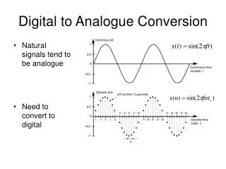
ADC • As mentioned before, most sensors of temperature, sound, and acceleration have analog outputs. However, these analog outputs have tobe converted intodigital signalsbefore they can be stored or used in calculations by the microcontroller. • Analogsignalsare convertedintodigitalrepresentationswitha resolutionandaratedeterminedbytheAnalogtoDigitalConverter (ADC). • AnADCisa circuitwhosedigitaloutputisproportionalto theanalog input. • Effectively, an ADC measures the input analog voltage, and gives a binaryoutputproportionaltothesize oftheinputsignal. • TheinputrangeoftheADCisusuallydeterminedbythevalueofa voltagereference (3.3 V)
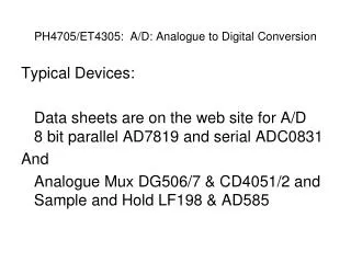
ADC Block Diagram • The conversion process is started by a digital input calledSC, start convert. • It takes a finite time to performtheconversion,depending on the clockfrequency. • The ADC signals that theconversioniscompletedvia the EOC, end of conversionline • The resulting data can then be written onto the output data bus, when the output enable,OEcontrolline, is high. Voltage Reference + + Analogue toDigital - Converter Analo gue + Analog Input Digital Output (n bits) uuee toDigital Converter - SC (Start Convert) EOC (Endof Conversion) OE (Output Enable) Example ControlLines
2 bit ADC http://www.asdlib.org/onlineArticles/elabware/Scheeline_ADC/ADC_ADC_Flash.html
ManyADCsfollowtherelation where: • Dis the digitaloutputvalue • Viis the analoginputvoltage • Vristhe referencevoltage • nis thenumberof bits in the converteroutput • How many voltage comparators are needed for a 12-bit ADC?
The output binary number is an integer, and for an n-bit number can takeanyvaluefrom0to(2n – 1 ). • Youmaywanttothinkaboutthis. • The ADC process rounds(truncates)the calculation to produce an integer output. • AnADCwillhavemaximumandminimuminputvaluesthatitconvert. Thedifferenceisthe range. • Oftentheminimumvalueis0 V,sotherangeisthenjustthemaximum possibleinputvalue. Analoginputvaluesthatexceedthemaximumorminimumwilllikelybedigitizedasthemaximumorminimumvalues (a limitingorclippingactionoccurs).
3 bit ADC • Thisshowsthatinmakingtheconversion,anapproximationisinvolved asanyonedigitaloutputvaluehastorepresenta rangeofanaloginput signals. • For example, if the output value of 100 is precisely correct in the middleofthestep, thegreatest errorswilloccurateither end. Asinputvoltage goesfrom 0VtoVmax, the digital outputwillstepfrom0to111or(23-1) Range of analogvalues allrepresentedby100
Errormadeby ADC From Understanding Data Converters, Texas Instruments Application Note
Quantisation Error • Thegreatestquantisationerrorisonehalfofthestepwidth,orhalfof oneleast significantbit(LSB)equivalentonthevoltagescale. • Toreducethe quantisationerror, the “stepwidth”shouldbe narrowed. Thiscanbe achieved by increasingthe numberofbits inthe ADCprocess. • This increases complexity and cost, and often the time taken to undertakethe conversion. • Whatis the step width andworstcasequantisationerror? • The LPC1768 ADC is 12 bit. • The reference voltage is taken from the regulated 3.3V supply.
Effectof QuantizationError QuantizationNoise eg 8bits A/D‐> noise flooris~ 50dB From Understanding Data Converters, Texas Instruments Application Note
Sample and Hold • Whenperforming ananalogtodigitalconversion,a“sample”istakenof analogsignalandquantized tothe accuracydefinedby theresolutionof theADC. • The signal is held, which means that it is stored temporally while the signal is compared to the reference voltage and the digital signal is generated. • Sometimes, the digital signal is generated by averaging the results of several analog samples. Themoresamplestaken,the moreaccuratethe digitaldatawillbeas long as the analog signal is not changing. • Samplingisgenerallydoneata fixed frequency, called the sampling frequency.
http://www.seas.upenn.edu/~ese206/labs/adc206/adc206.html S&H – Sample and Hold Decoder – circuitry to change outputs of the n comparators to the digital signal.
Theideal samplingfrequencydependsonthemaximumfrequencyofthesignalbeingdigitised.Ifthesamplingfrequencyistoolow,thenrapid changesintheanalogsignalmaynotberepresentedintheresultingdigitaldata. Sampling Frequency Waveformsshowing that undersamplingresults in the digitisedoutput(lower traces)notrepresenting theinputwaveforms(upper traces)
Nyquist-Shannon Sampling Theorem • TheNyquist-Shannon samplingcriterionstatesthat the samplingfrequencymust be atleastdoublethatofthe highestfrequencyofinterest. • However, it is generally agreed that the sampling frequency should be 5+ times the highest frequency found in the analog signal. • If the highest frequency that is created when a human speaks is 3.5 kHz, what is the minimum sampling frequency that should be used? • The name of the criterion is usually shortened one or the other names – Nyquist criterion or Shannon Criterion.
Aliasing • Ifthe Nyquistcriteria isnotsatisfied,a phenomenonknownasaliasing occurs. Manyweirdandwonderfulthingscanhappen. • Two signals can have the same digitized output. • If thesampling frequencyis thesame asthe inputfrequency, theoutputisconstant! http://www.svi.nl/AliasingArtifacts
ADC/DAC Program /*Program to explore some of the time-related aspects of the mbed DAC and ADC/ #include "mbed.h" AnalogOut Aout(p18); AnalogIn Ain (p20); DigitalOut test(p5); float ADCdata; int main(){ while(1){ ADCdata=Ain; //Perform an ADC conversion test=1; test=0; //1 pulse on p5 shows end of the ADC conversion Aout=ADCdata; //Perform a DAC conversion test=1; test=0; test=1; //2 pulses on p5 shows end of the DAC conversion test=0; } }
Timingissuesand consequences DAC conversion DAC conversion ADCConversion Singlepulse Doublepulse Singlepulse Doublepulse
Switchingandigitaloutput onorofftakes~72 ns cf 1 clockperiod= 1/96MHz= 10.4 ns
Sampling rate /*Program to explore some of the time-related aspects of the mbed DAC and ADC/ #include "mbed.h" AnalogOut Aout(p18); AnalogIn Ain (p20); DigitalOut test(p5); float ADCdata; int main(){ while(1){ ADCdata=Ain; //Perform an ADC conversion test=1; test=0; //1 pulse on p5 shows end of the ADC conversion Aout=ADCdata; //Perform a DAC conversion test=1; test=0; test=1; //2 pulses on p5 shows end of the DAC conversion test=0; wait (0.001) // slows sampling rate } }
wait=1ms Maximumfrequency< 500Hz Ain= 200Hz Ain= 400Hz Ain= 500Hz Ain= 976Hz
wait=0ms.WhatisNyquistfrequency? Looks~ 44kHz. StandardaudioCDsaresampledatplayedbackat44.1kHz,to adhere to Nyquist sampling criteria as it relates to human auditorysystemwhichextendsto~20kHz. Coincidence?
SomeDACand ADCtiming issuesand consequences This is a bit strange, as from the LPC1768 User Manual Table531, A/DControlRegister Thisisthepriceweare payingforthe ease ofprogramming thembedusingtheC++functions.