Download
1 / 117
1.17k likes | 1.18k Views
JOINT ACCESS. CHIMERA CLASS. Joint ACCESS. High Speed Assault Connector. TSSE Design Team. Naval Postgraduate School. December 2, 2004. Amphibious Combat Cargo Expeditionary Support Ship. JOINT ACCESS. CHIMERA CLASS. TSSE Staff Prof. Fotis Papoulias Prof. Bob Harney

E N D
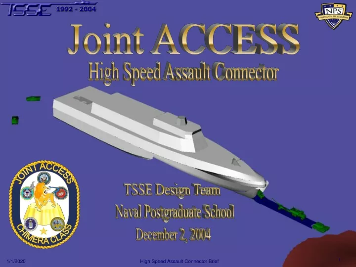
JOINT ACCESS CHIMERA CLASS Joint ACCESS High Speed Assault Connector TSSE Design Team Naval Postgraduate School December 2, 2004
Amphibious Combat Cargo Expeditionary Support Ship JOINT ACCESS CHIMERA CLASS
TSSE Staff Prof. Fotis Papoulias Prof. Bob Harney 2004 Design Team LT Timothy King, USNR, ECE LT Steven Peace, USN, SEA LCDR Paco Perez-Villalonga, ESP, OR LT Derek Peterson, USNR, MAE LT Rolando Reuse, CHL, MAE LT Scott Roberts, USN, MAE TSSE Team LTjg Kivanc Anil, TUR, MAE LTjg Mehmet Avcu, TUR, MAE LT Jon Brisar, USN, PHY LTjg Adnen Chaabane, TUN, IW LTjg Sotirios Dimas, GRC, MAE LT Matt Harding, USN, MAE 12 Students 6 Countries 6 Departments
Today’s Agenda Introduction Mission Flexibility Summary Manning/ Habitability Requirements & Design Combat Systems Cargo Damage Control Hull Propulsion Electrical
The Request • A conceptual design for a High Speed Assault Connector (HSAC) to enhance Joint Expeditionary Logistics (JELo) flow from the Sea Base to shore • Augment or replace existing connector platforms • Employment requirement • Cargo: ~8000LT of vehicles, troops, and gear • Distance: 200nm from the Sea Base to shore • Time: 10 hours • Sea state: 4 • Interface: accept cargo and troops at the Sea Base and deliver to shore
The Design Solution • A system of 12 HSACs that fill all the previous connector requirements • Each HSAC is multi-mission capable, self-sustaining, and: • Can accommodate embarked troops, cargo, and gear from FLS and or/CONUS to the Sea Base • Can transit 2000nm @20kts (fully loaded) w/40% fuel remaining • Has defensive and offensive combat capabilities
Introduction Mission Flexibility Summary Manning/ Habitability Requirements & Design Combat Systems Cargo Damage Control Hull Propulsion Electrical
Initial Requirements • SEA-6 • Transport JEB from the Sea Base to shore • Time limited to a 10 hour period • Interface with Sea Base, developed ports, and austere beaches • TSSE Faculty • Support amphibious operations ashore in addition to delivering payload • Conduct secondary missions • Capable of independent operations
Assumptions • HSAC will move entire surface component of JEB • 2 Battalion Landing Teams (BLT) • HSAC fully loaded prior to employment phase • HSAC transit protected by the Sea Shield provided by Sea Base forces • Landing operations will be conducted in reduced threat environments • Boat lanes will be mine free
Beachable/Non-Beachable • Considered two delivery methods • Beachable • Non-Beachable (LCAC ferry) • Conducted feasibility study on both
Non-Beachable Feasibility • Pros • Information readily available • Few tactical changes required • Improves effective LCAC range • Proven, beachable, high-speed connector • Cons • Large number of LCACs required • LCACs approaching end of service life • Inadequate availability/reliability • Additional interface in the loop
Beachable Feasibility • Analysis of Newport class LST • 3000LT payload • 16 ft draft • Bow ramp and stern gate • Pros • Performed similar mission • Large craft can be made beachable • Newer technologies will greatly enhance the capabilities of previously proven designs • Provides a single connector solution • Cons • Structural issues for bow ramp/beaching • Possibly hull form limiting • Beachable design selected
Analysis of Alternatives • Developed 3 Measures of Performance (MOP) • Analytic Hierarchy Process (AHP) was used to set the weights • Transport factor – 43% • Survivability – 43% • Number of ships – 50% • Overall ship length – 30% • Speed – 20% • Mission flexibility – 14% • Payload – 30% • Draft – 30% • Number of ships – 20% • Speed – 20% • Overall MOP weighted sum of the individual MOPs
Design of Experiments • 7 x 9 x 5 Design matrix • 7 different hull types • 9 different payloads • 5 different speeds • Total of 315 possible designs • Initial ship characteristics calculated using software from Maritime Applied Physics Corporation at MIT
AoA: Score Criteria • 315 designs were evaluated using TSSE generated MOPs • 292 designs were eliminated based on these MOP score criteria • Average MOP < 0.4 (REJECT) • (MOPmax – MOPmin) > 0.05 (REJECT) • Average > 0.45 or passes tests 1 and 2 (ACCEPT) • 23 remaining designs were plotted vs. cost to determine the optimum design
Trimaran Catamaran HYSWAS AoA: MOP vs Cost Better
Sensitivity Analysis • Same 3 Measures of Performance (MOP) • Transport factor – 33% • Survivability – 33% • Mission flexibility – 33% Trimaran Better
Beachable Trimaran • Beachable design • Smallest average draft (17ft) • Greatest number of retained alternatives • Highest overall MOP among hull types • For each speed • For each payload • Highest overall MOP for one of the lowest costs • Only cheaper alternatives were HYSWAS and a point solution monohull, both with deep drafts
Introduction Mission Flexibility Summary Manning/ Habitability Requirements & Design Combat Systems Cargo Damage Control Hull Propulsion Electrical
204 Humvee 98 EFV 21 M1A2 4 AVB 2 AVLB 8 M9ACE 2 M88A2 16 ITV 10 Avengers 38 MTVR 12 LW155 16 M105 6 MK155 34 M101 2 M149 2 M116 2 AN/TPQ 8 4K Forklifts 4 Contact trucks Cargo Requirements • Transport surface components of 2 Battalion Landing Teams • A total of 546 vehicles delivered in first 10 hours
Cargo Distribution • One BLT can be transported on 6 ships • Provides for mission scalability • Provided greater load-out flexibility • Vessel load-outs • Load-outs fell below maximum payload • Maximum design payload = 800 LT • Heaviest load-out = 693 LT • Average load-out = 663LT
Cargo Distribution • Distribution of (1) BLT aboard (6) HSAC
Cargo Interfaces • Stern gate/ramp • Cargo decks • Flight deck & elevator • Bow ramp
Stern gate • Allows interface with Sea Base and pier via Mediterranean mooring • Hydraulically operated • 120 degree range of motion from vertical to partial submersion • Supports deployment/recovery of EFV • Can be accomplished with current RO-RO technology
Cargo Layout • Upper and lower cargo deck • Heaviest equipment stored on lower deck and centerline of upper deck • M1A2, EFV, ABV, M88ACE, AVLB • Lower deck access from stern gate and bow ramp • Upper deck access from forward and aft fixed ramps • Ventilation system on both decks will handle removing vehicle exhaust from the ship
Flight Deck & Elevator • Flight deck supports CH-53X, MV-22, and SH-60R • Hangar for 1 SH-60R • Elevator provides access to flight deck from cargo decks • Allows vertical replenishment of oversized and palletized supplies • Allows vertical delivery of vehicles/equipment from cargo decks to shore • Supports use of upper cargo deck as hangar for multiple SH-60R (BLT not embarked)
Bow Doors • 5m x 6.2m opening in bow • Facilitates ramp deployment and vehicle offload • Doors constructed from composite materials • High strength, low weight • Hydraulically actuated • Eliminates hinges • Reduces the amount travel required for opening • Watertight door aft of bow doors ensures watertight integrity • Armored to provide protection during landing ops
Bow Ramp • Sectional floating causeways • Maximum deployed length = 35m • (8) 5m x 5m x 1.6m sections • Allows variable deployment length • Supports maximum load of (2) M1A2 Tanks • Stored below lower cargo deck • Mechanical deployment and recovery • Deployment/recovery rate = .2 m/s • Maximum length deployment ~ 3min
Introduction Mission Flexibility Summary Manning/ Habitability Requirements & Design Combat Systems Cargo Damage Control Hull Propulsion Electrical
Hull Form: Trimaran • Pros • Low resistance • Large deck area in upper decks • Enhanced stability • Cons • Little information available = higher risk • Less space in lower decks • Limited bow ramp width
Trimaran Feasibility • Existing or projected trimarans • Length/beam ratio ~ 13 - 15 • Froude number ~ 0.4 – 0.5 • Payload ~ 30 - 40% displacement • Overall length ~ 140 - 160m http://www.gomeralive.de/fred-olsen.4021.0.html
Alternative Center Hull Forms • Hull form A • Lowest wave resistance • Deepest draft • Hull form B • Minimal wetted surface • Intermediate draft • Intermediate beam • Hull form C • Greatest wave resistance • Lowest draft
Selected Hull Form • Wetted surface = 4300m2 • Length = 149m • Beam = 13m • L/B = 11.5 • Froude number = .51 • Draft = 4.5m
Draft Constraint • Slope 1:30 • Parabolic keel line • Reduced forward draft
Calculations • Hydrostatics • Cross curves • Tankage • Stability • Damaged stability
Operating Envelope Reality Check
Introduction Mission Flexibility Summary Manning/ Habitability Requirements & Design Combat Systems Cargo Damage Control Hull Propulsion Electrical
Electric Drive • Pros • Increased flexibility over mechanical drive • Long drive train not required • Prime movers’ location not restricted • Power available for other uses • Increased fuel efficiency • Cons • Not proven • Electric drive selected
Power Requirements • Combat systems and other electric loads: 2 MW • Propulsion: Total power for 43 knots: 60 MW