Download
1 / 8
80 likes | 228 Views
F8S1 – Wind Siting. Within the MISO footprint, a set of renewable energy zones focusing on wind capacity were developed through extensive work with stakeholders

E N D
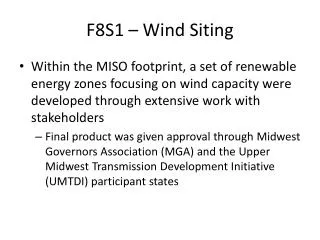
F8S1 – Wind Siting • Within the MISO footprint, a set of renewable energy zones focusing on wind capacity were developed through extensive work with stakeholders • Final product was given approval through Midwest Governors Association (MGA) and the Upper Midwest Transmission Development Initiative (UMTDI) participant states
F8S1 – Wind Siting • The development of the zones focused on the identification of high capacity factor wind areas in each of the states • Intent of the zone development was to balance high capacity factor regional resources with local investment opportunity • Regional planning is being implemented based on these zones and therefore these zones are highly likely to be where renewable energy will locate, and should be the primary location for the distribution of wind within the MISO footprint
F8S1 – Wind Siting • Premise of zone development was to have equivalent maximum capability in each zone. • Resulted in a 55/45 split between siting of wind in the MISO West region to the rest of the footprint • The distribution of wind in the EIPC has roughly 60% of the forecast wind in the West subregion compared to the rest of the footprint. • Roughly comparable to the initial intent of the MISO RGOS zone development • Because of the assumption of equivalent capacity in each zone in the MISO process, it is proposed that the EIPC distribute the non MISO West wind (40% of total MISO wind identified) as equivalent capability in each of the identified MISO RGOS zones
MISO W • When this approach is used to redistribute the non-West wind additions from the F8S1 case, the results are as shown MISO WUMS 60,831 MISO MI 7,894 15,787 MISO MO/IL 5,262 10,525 MISO IN
F8S1 – Wind Siting for Non MISO West Wind 39,468 MW spread over 15 zones results in a distribution of 2,631 MW per zone, consistent with the methodology applied to the MISO Regional Planning process.
F8S1 – Combined Cycle Siting • Significant retirements identified within the MISO footprint. The spread of the retirements appears to be fairly balanced between the NEEM regions for the MISO system. • It is recommended that the combined cycle build be distributed at the same ratio of how the retirements occurred • Will support locational reserve requirements • Will support local transmission thermal and voltage support • Reasonable assumption that repower of retirement sites may be cheaper than the greenfield sites that are being modeled
F1S3 Combustion Turbine Siting • Combustion turbines are generally being added to meet resource adequacy needs with minimum energy dispatch • To meet more of the locational nature of resource adequacy needs, it is recommended that the peaking capacity be spread through the various NEEMS regions based on a load or energy ratio distribution for the MISO system • This will provide a distribution of the capacity with minimal effect on the transfer of economic energy across the system
F6S10 Combustion Turbine Siting • Utilize same methodology in F1S3 for first 4,597 MW • For the remaining 7,092 MW, distribute the CT build to co-locate with wind capacity • Distribute by the proportion of cumulative wind builds in the scenario • Allows for operational coordination between fleets to utilize the same transmission