Download
1 / 72
720 likes | 890 Views
The International Linear Collider (ILC) – Status and Dubna Siting Grigori Shirkov Dubna, July 26, 2006. Международный Линейный Коллайдер. Linear Collider – two main challenges. Energy – need to reach at least 500 GeV CM as a start Luminosity – need to reach 10^34 level.

E N D
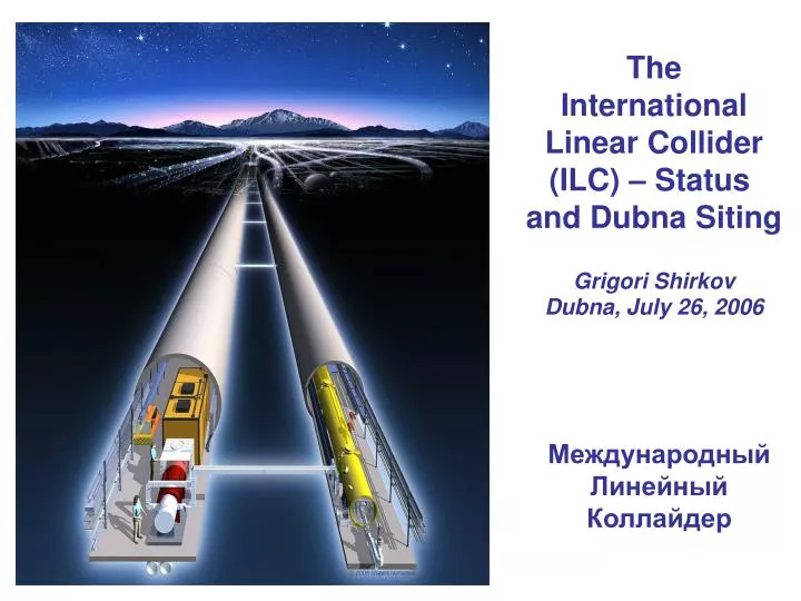
The International LinearCollider (ILC) – Status and Dubna Siting Grigori Shirkov Dubna, July 26, 2006 Международный Линейный Коллайдер
Linear Collider – two main challenges • Energy – need to reach at least 500 GeV CM as a start • Luminosity – need to reach 10^34 level
Luminosity & Beam Size • frep * nb tends to be low in a linear collider • The beam-beam tune shift limit is much looser in a linear collider than a storage rings achieve luminosity with spot size and bunch charge • Small spots mean small emittances and small betas:sx = sqrt (bxex)
Beam Parameters • Requirements: • High luminosity – set by physics needs • Low backgrounds (small IP effects) • Forced to high beam power and small vertical spots • Details of technology determine other limitations • Rf cavities and power sources 10 mA beam current • Damping rings beam emittances and number of bunches • Bunch compressors IP bunch length • Cryogenic systems duty cycle • Extensive cost optimization is required to balance systems • Linear collider will push many technological and beam-physics limits • Need to have operational flexibility to overcome unexpected problems
ILC Parameters Parameter range established to allow for operational optimization
Schematic of the ILC e-(e+) source and delivery system Main Linac (ML) Damping Ring(s) Beam Delivery System (BDS) Ring(s) To Main Linac (RTML system) Beam Dump (BD)
1st stage ILC : 500 GeV 2nd stage ILC : 1 TeV - extension of main linac - moving of SR and BC
sub-harmonic bunchers + solenoids ILC Gun Schematic View laser standard ILC SCRF modules room-temperature accelerating sect. Guns diagnostics section DC gun: 120 keV HV Laser requirements: pulse energy: > 5 uJ pulse length: ~ 2 ns # pulses/train: 2820 Intensity jitter: < 5 % (rms) pulse spacing: 337 ns rep. rate: 5 Hz wavelength: 750-850 nm Photocathodes: GaAs/GaAsP strained super-lattice Room temperature linac: Allows external focusing by solenoids Same as e+ capture linac
ILC Gun Beam Specifications • Polarized electrons are produced by injecting circularly polarized photons(sz=±1) on NEA GaAs cathode.
OPCPA (Optical Parmetric Chirped Pulse Amplification) system generates trains with a wide range of pulse length, 150 fs .. 20 ps (FWHM) • Pulse energy: Emicro = 50 ~ 100 uJ Etrain = up to 80 mJ • Available wavelength: = 790 ~ 830 nm • Pulse train: up to 0.9ms Output pulse train of the OPCPA ILC Gun Multi Bunch Laser I. Will, H. Redlin, MBI Berlin up to 900 us
Damping Rings • Damping rings have more accelerator physics than the rest of the collider • Required to: • Damp beam emittances and incoming transients • Provide a stable platform for downstream systems • Have excellent availability ~99% (best of 3rd generation SRS) • Mixed experience with SLC damping rings: • Referred to as the “The source of all Evil” • Collective instabilities; Dynamic aperture; Stability • Damping ring designs based on KEK ATF, 3rd generation SRS, and high luminosity factories • Experimental results provide confidence in design
Issues in the Damping Rings • Emittance tuning and error correction • Orbit correction and component stabilization • Injection/extraction of individual bunches • Kicker rise/fall time – very large rings to store 3000 bunches • Dynamic aperture • Long wigglers needed if the ring is too big • Single-bunch intensity • Tune shift by self-Coulomb force (space charge) • Instabilities (mainly average current) • Electron cloud instability • Fast ion instability • Classical collective instabilities • Rings operate in a new regime with fast dampingand very small beam emittances
An aside: the damping wiggler • The damping time in a storage ring depends on the rate of energy loss of the particles through synchrotron radiation. In the damping rings, the rate of energy loss can be enhanced by insertion of a long wiggler, consisting of short (~ 10 cm) sections of dipole field with alternating polarity. y z x The magnetic field in the wiggler can be approximated by: By = Bw sin(kzz)
Main Linac Design • Baseline Configuration Document (BCD) distilled from Snowmass Working Group recommendations in August 2005. • Major differences from 2001 Tesla TDR 500 GeV Design. • Higher gradient (31.5 MV/m instead of 23.4 MV/m) for cost savings. • Two tunnels (service and beam) instead of one for improved availability. • The Linac Area Group of the Global Design Effort (GDE) is continuing to evolve design.
Technical Challenges at the ILC Superconducting RF Acceleration technology - Nano-meter size beam handling technology Laser wire system
電場 (陽)電子 Acceleration Electric Field Electron (positron)
Multi-cell Structures and Weakly Coupled StructuresCavities ● Field flatness vs. N Field flatness factor For the TESLA cavities: field flatness is better than 95 %
1.3 GHz TESLACavities • Made with solid, pure niobium – it has the highest Critical Temperature (Tc = 9.2 K) and Thermodynamic Critical Field (Bc ~ 1800 Gauss) of all metals. • Nb sheets are deep-drawn to make cups, which are e-beam welded to form cavities. • Cavity limited to ~ 9 cells (~ 1 m Long) to reduce trapped modes, input coupler power and sensitivity to frequency errors. • Iris radius (a) of 35 mm chosen in tradeoff for low surface fields, low rf losses (~ a), large mode spacing (~ a3 ), small wakes (~ a-3.5 ).
Cryomodule Design Relative to the TTF cryomodules • Continue with 8 cavities per cryomodule based on experience and minimal cost savings if number increased (12 in TDR). • Move quad / corrector / bpm package to center (from end) to improve stability. • Increase some of cryogenic pipe sizes (similar to that proposed for the XFEL). • Decrease cavity separation from 344 mm to 283 mm as proposed in the TDR.
Niobium:Electron Beam Melting • High Purity Niobium(RRR>250) is made by multiple electron beam melting steps under good vacuum, resulting in elimination of volatile impurities • There are several companies, which can produce RRR niobium in larger quantities: Wah Chang (USA), Cabot (USA), W.C.Heraeus (Germany), Tokyo Denkai(Japan), Ningxia (China), CBMM (Brasil) EBM Ingots at CBMM CBMM deposit in Araxa, Brasil EBM furnace at Tokyo Denkai
Cavity Tests on Mono-cells - dedicated nozzle system for cavity cleaning developed[L.Lilje, CARE Meeting Nov. 2004, DESY]
Fabrication • Hydro forming (W.Singer,DESY)Spinning (V.Palmieri,INFN Legnaro)
Beam Delivery System challenges • Focus the beam to size of about 500 * 5 nm at IP • Provide acceptable detector backgrounds • collimate beam halo • Monitor the luminosity spectrum and polarization • diagnostics both upstream and downstream of IP is desired • Measure incoming beam properties to allow tuning of the machine • Keep the beams in collision & maintain small beam sizes • fast intra-train and slow inter-train feedback • Protect detector and beamline components against errant beams • Extract disrupted beams and safely transport to beam dumps • Minimize cost & ensure Conventional Facilities constructability
Beam Delivery System • Requirements: • Focus beams down to very small spot sizes • Collect out-going disrupted beam and transport to the dump • Collimate the incoming beams to limit beam halo • Provide diagnostics and optimize the system and determine the luminosity spectrum for the detector • Switch between IPs
5 500 300000 How to get Luminosity • To increase probability of direct e+e- collisions (luminosity) and birth of new particles, beam sizes at IP must be very small • E.g., ILC beam sizes just before collision (500GeV CM):500 * 5 * 300000 nanometers(x y z) Vertical size is smallest
Modulators (115 kV, 135 A, 1.5 ms, 5 Hz) (~ 2 m Long) To generate pulse, an array of capacitors is slowly charged in parallel and then discharged in series using IGBT switches.Will test full prototype in 2006 Pulse Transformer Style
Thales CPI Toshiba Klystrons Baseline: 10 MW Multi-Beam Klystrons (MBKs) with ~ 65% Efficiency: Being Developed by Three Tube Companies in Collaboration with DESY
Beam dump for 18MW beam • Water vortex • Window, 1mm thin, ~30cm diameter hemisphere • Raster beam with dipole coils to avoid water boiling • Deal with H, O, catalytic recombination • etc.
The Big Picture: ILC Site Power~ 330MW Sub-Systems 60MW Main Linacs 140MW RF: 90MW Injectors Cryogenics: 50MW Damping rings 78% BDS Auxiliaries 65% 60% Beam 22MW
International Organization Definitions ICFA - International Committee for Future Accelerators FALC - Funding Agencies for the Linear Collider ILCSC - International Linear Collider Steering Committee GDE - Global Design Effort RDB - Research and Development Board CCB - Change Control Board DCB - Design Cost Board CFS - Conventional Facilities and Siting BCD - Baseline Configuration Document RDR - Reference Design Report TDR - Technical Design Report WBS - Work Breakdown Structure
International Linear Collider Timeline 2005 2006 2007 2008 2009 2010 Global Design Effort Project Baseline configuration Reference Design Technical Design ILC R&D Program Expression of Interest to Host International Mgmt
EUROPEAN SAMPLE SITE - CERN Longitudinal Section
EUROPEAN SAMPLE SITE - DESY Longitudinal Section
ASIAN SAMPLE SITE Longitudinal Section
AMERICAS SAMPLE SITE Longitudinal Section
ILC Tunnel Layout For baseline, developing deep underground (~100 m) layout with 4-5 m diameter tunnels spaced by 5 m.
MAIN LINAC SERVICE TUNNEL VENTILATION Normal airflow for 1 mile per hour speed= 19,000 cfm dry 100% outdoor air per tunnel = 0.3 airchange per hour at 5 meter diamater tunnel. Airflow increase per CO2 sensor. Smoke airflow (TBD) Assume 2X = 38,000cfm (placeholder) ODH airflow (NONE). Service tunnel to be separated from Cryo cavern Construction Airflow (not included) Thermal load Airflow (Not included). Heat load to air will be handled by separate chilled water fancoils (see sketch) MAIN LINAC BEAM TUNNEL VENTILATION Normal airflow same as Service tunnel Smoke airflow (TBD) Assume 2X = 38,000cfm ODH airflow (TBD). Construction Airflow (not included) Thermal load Airflow (Not included). Minimal load to air
EXTENT OF CONSTRUCTION • Main Accelerator Enclosures - 475,000 m3 • Main Accelerator Support Enclosures - 475,000 m3 • 2 Damping Ring Enclosures - 210,000 m3 • 12 Access Shafts - 70,000 m3 • Beam Delivery Enclosures - 160,000 m3 • 2 Interaction Halls - 800,000 m3 • Additional Support and Transport Enclosures - 300,000 m3 • Surface Facilities - 85,000 m2
Side View of Shielded Tunnel Boring Machine -W. Bialowans
Cutting Face of Modern Tunnel Boring Machines -W. Bialowans
Cryogenic Plants Water Processing Plants