Download

1 / 13
130 likes | 250 Views
Bread Boarding and Operating. The IFI Robotic Control System. This Slide Show will help the BattleBots IQ Participants:. Become familiar with the parts and terminology associated with the basic operation of the IFI Robot control system.

E N D
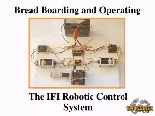
Bread Boarding and Operating The IFI Robotic Control System
This Slide Show will help the BattleBots IQ Participants: Become familiar with the parts and terminology associated with the basic operation of the IFI Robot control system. Set up and operate the IFI Robot Control system using the default control functions. There is no substitute for reading the IFI Manual! Download it now!
The IFI Robot Control System The IFI Robot Control System is comprised of two sub systems The Operator System and the Robot Control System The Operator system This System accepts control inputs from the human operator through joysticks, switches and potentiometers. The systems also displays input/output data sent to and received from the robot Robot Control System Includes “Onboard” IFI control components such as the Robot Controller, Data Modem, PC board, Victor Speed Controllers and Spikes.
The IFI Robot Control System The Robot Controller The IFI Robot Control System Components: 1.) Programmable Robot Controller and Data Modem 2.) Mechanically mountable PC Board with PWM and relay connectors, serial port, and LED status display. 3.) Victor PWM speed controllers 4.) IFI Spike Relay controller. Slides 5 – 12 describe the parts and illustrate the basic set up of the Robot Controller.
Robot Controller System Potentiometers 0-5v Sensors Master Processor 1.) Receive data from Radio 2.) Read analog Inputs (on robot) 3.) Read digital Inputs (on robot) 4.) Send Data to BS2SX 5.) Send Data to Radio 6.) Repeat Switches BS2SX(Pbasic Processor) Servos Speed Controllers 1.) Input Serial Data 2.) Process Data 3.) Output Dashboard Bits 4.) Output Serial Data 5.) Repeat Small Motors, Solenoids, Lights Output Processor 1.) Input Serial Data 2.) Output PWM Signals 3.) Output Relay Signals 4.) Repeat
The IFI Robot Control System The Robot Control Module The Robot Control Module Contains: Radio, Input Processor, Pbasic Processor, Output Processor The Robot Control Module plugs into dual “keyed” 40 pin headers on the underside of the Robot Control PC Board. The PC Board is populated with input/output pins, a PBASIC memory Chip, fuse, Team ID dips and an LED Status Display.
The IFI Robot Controller PC Board Digital Inputs sw 1-sw 8 Status LED’s Digital (Relay) Outputs RLY1-RLY4 Mounting Holes Programming/Tether Port Program/Tether Switch Team DIP Switch Power Switch Battery Connector Analog Outputs PWM Analog Inputs AN1 – AN4
Connecting the Victor Speed Controller To 12V Battery + To PWM 1 + To Traction Motor Robot Controller PC Board
IFI Robot Control System Victor PWM Speed Controller Wired to a modified drill motor and transmission + +
Connecting the IFI Spike The Spike is a 20 Amp H-Bridge relay controlled by a PWM Output on the IFI Robot Controller PC Board To 12V Battery + PWM To RLY1 + To Weapon Motor, Relay, etc. Robot Controller PC Board
IFI Robot Control System Spike 12V Gnd Positive 12V Buss Spike wired to actuate the solenoid of an SMC Pneumatic valve
Weapon System Right Motor Left Motor - - + + Computer SPIKE Speed Controllers M+ M- M+ M- gnd 12V+ - - + + Fuses To PWM1 Relay 1 To PWM2 + - 12 Volt Battery Robot Controller Schematic
The Operational Robot Control System CAUTION: ALWAYS OBSERVE POLARITY!