Download
1 / 15
150 likes | 258 Views
Improved beam line for Hall A. layouts, present and proposed optics in altered region benefits of proposed layout costs of proposed layout conclusions. layouts – present and proposed. ep not possible after Moller scattering (per Kees).

E N D
Improved beam line for Hall A layouts, present and proposed optics in altered region benefits of proposed layout costs of proposed layout conclusions
layouts – present and proposed ep not possible after Moller scattering (per Kees) 1m of 10cm tube with H/V corr, 3” BPM, switch to 2.5cm tube, quad, 2m fast raster, BPM, H/V correctors 4.5m available where ep is shown, not 5m
Optics plots 2 (combined optics) p extent BPM PIVOT BPM TargetRaster Moller raster PIVOT MOLLER Target
Smaller spot at target Betas (top) and beam envelopes (bottom) with minima 5m upstream of pivot. Is this better or worse for beam spot size stability give slow 0.05% changes in quads?
Benefits • fast raster after all quads so it’s always what you set • quads after Compton may be set for target beam size and BPM phase advance • better control of beam size due to new quad locations • more correctors and BPMs to eliminate scraping and improve orbit locks • better control of orbit through raster and eP due to new BPMs and correctors • fewer ion chamber trips • double raster length eases engineering for 11 GeV • 4.5m drift before diagnostic girder allows for either eP system or MOLLER target insertion • high current Moller polarimetry feasible via combined optics
Costs • Existing fast raster system mounted on leg of Compton before the electron detector as Moller raster. +-250 microns at electron detector, $5K • Single QR or QA-pair inserted between 1C18 A/B harps on “French bench”. $45K • GEANT simulations to determine effects of elements on 1” beam pipe after Moller spectrometer dipole and the shielding changes needed as a result. We need to keep S/N up in Moller polarimeter detectors. • ME design ~$100K • Two girder extrusions and two stands, one extending inverted girder ~$20K • Three additional BPMs and electronics ~$36K • S/H cards for new BPMs $30K?? • Three additional H/V corrector sets and power supplies ~$24K • New fast raster system $100K?? • If eP not retained, yet another BPM/corrector pair in that drift, $20K • 1H00 harp omitted. May fit immediately after IBC/IUN/IBC as it’s mounted there now – I need more accurate dimensions. Can it be moved next to IPM1P03A? This allows better optics control at the Compton electron-laser interaction point. New vacuum vessel will be needed for this region as the middle Compton dipoles move up 8 cm. Add NEG pumps to improve vacuum near electron detector. • quad upgrades not in 12 GeV project: two 20A power supplies
Further work needed • Layout to pin down locations to centimeters (Accelerator and Engineering) • 11 GeV raster design: 40% longer coil and power supply with twice the voltage, 40% more current. If the pair of coils of the same plane must be driven in series, four times the voltage and 1.4 times the current. (TBD) • Moller polarimeter dipole and detector S/N modeling; shielding design with BPMs, correctors and rasters where 4” pipe now exists. Primary beam through Moller dipole – what corrector strength is needed? (Hall A collaboration) • Combined optics must be implemented to allow high current Moller polarimetry. This requires one quad between the Moller dipole and the fast raster, increasing design problem of the latter. It will also constrain either beam size or phase advance in 7m before target. (Physics and Accelerator)
Conclusions (1) • A rearrangement of the Hall A line is proposed which removes a severe optics constraint, raster performance • Beam quality will be improved for all experiments, especially 11 GeV parity experiments including MOLLER. • Ion chamber trips will be reduced, improving availability and reducing irritation in MCC and the other halls • Cost of order $0.8M: design, procurements, installation
ep system • The ep system is not functional. • It is very difficult to steer in the Compton with the ep ion chambers set to trip at low values. • Compton optics matching will take several hours and disrupt the other halls unless one hour mask durations may be applied to Compton and ep ion chambers during optics data acquisition using harps. • Do any of the remaining 6 GeV experiments require the ep system? Will the system be of any use at higher energy? • Might the system be easier to repair if removed from the hall during January 2010? Replace with 10 cm beam tube for vacuum conductance.
UVa Polarized target chicane • 2007 design for g2p requires removal of Moller polarimeter shielding, inverted quad girder, and final diagnostic girder for vertical chicane. Moller polarimeter will be non-functional. • Proposed design has room for vertical chicane after final correctors, in space designated for ep and final diagnostic girder. Moller polarimeter intact. • Space for second fast raster in proposed design may be occupied by slow raster. • Tungsten calorimeter can substitute for Unser and second BCM as on next slide.
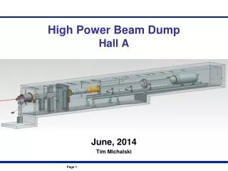
Beamline Chicane EP Moller Target center • Chicane Design : Jay Benesch (JLab CASA) • Two upstream Dipoles, one with vertical degree of freedom. • Reuse the dipoles from the HKS experiment. • Utilize open space upstream of target. • Minimal interference with existing beamline equipment. Major Installation UVA/Jlab 5 T Polarized Target Upstream Chicane and supports Slow raster and Basel SEM. Instrumentation for 50-100 nA beam. Local beam dump. Hall A Septa.
layouts – g2p and this proposal 1m of 10cm tube with H/V corr, 3” BPM, switch to 2.5cm tube, quad, 2m fast raster, BPM, H/V correctors 4.5m available where ep is shown, not 5m
The Experiment Data Taking 15.7 Qweak has polarization control for g2p @ 2.2, 3.3 and 4.4 GeV Overhead 8.4 Total Days 24.1
Conclusions (2) • The ep system should be removed from the hall ASAP. Repair offline if the collaboration wishes. • The proposed Hall A line is more compatible with the vertical chicane needed for the UVa polarized target and g2p than is the present line. • If mechanical design begins in January 2010 and labor is available it should be possible to install the new line and g2p in the six month 2011 down. • BTW – I hope you’ve got the He3 needed for the dilution refrigerator. DHS has exhausted the supply.