Download
1 / 28
280 likes | 390 Views
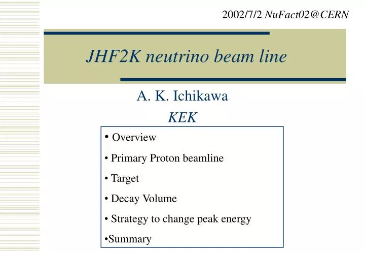
2002/7/2 NuFact02 @ CERN. JHF2K neutrino beam line. A. K. Ichikawa KEK. Overview Primary Proton beamline Target Decay Volume Strategy to change peak energy Summary. Overview of experiment. Conventional n m beam of ~1GeV. Kamioka. Super-K: 50 kton Water Cherenkov . JAERI

E N D
2002/7/2 NuFact02@CERN JHF2K neutrino beam line A. K. Ichikawa KEK • Overview • Primary Proton beamline • Target • Decay Volume • Strategy to change peak energy • Summary
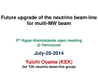
Overview of experiment Conventional nm beam of ~1GeV Kamioka Super-K: 50 kton Water Cherenkov JAERI (Tokai-mura) 0.75MW 50 GeV PS ~Mt “Hyper Kamiokande” 4MW 50GeV PS 1st Phase 2nd Phase • nm→ nx disappearance • nm→ neappearance • NC measurement • CPV • proton decay
Far Det. q Decay Pipe Target Horns OA1° OA2° OA3° Off Axis Beam Osc. Prob.=sin2(1.27Dm2L/En) (ref.: BNL-E889 Proposal) Dm2=3x10⁻³eV2 L=295km osc.max. nm • Quasi Monochromatic Beam • x2~3 intense than NBB Tuned at oscillation maximum Exp’ed # of evts(1yr,22.5kt) ~4500 nm tot ~3000 nm CC ne contamination ~0.2% at nm peak (OAB 2degree) Expected spectrum (OAB2o) ~102 x (K2K)
Overview of Facility Primary Proton beamline Target Station Decay Volume m pit SK Beam Axis 280m Near Detector 50GeV PS
Overview -Primary proton beamline- Preparation section Arc R=106m • Single turn fast extraction • 8 bunches/~5ms • 3.3x10¹⁴proton/pulse • 3.94 (3.64) sec cycle • 1yr≡1021proton on target(POT) • e=6p mm.mr Final Focusing Section
Beam loss 50GeV ring 0.5W/m Fast ext.(kicker, septum) 1.125kW (0.15%) • No way to know absolute beam loss • Assumed by HAND • Assure hands on maintenance (1W/m) • Shielding design based on the assumption • Same order as KEK-PS beam line • ~102 relative suppression!!Challenging 1W/m along beam line Matching section (ctrl’ed loss by collimator) 0.75kW (0.1%)
V e=24p Collimator/shield monitor Matching Point 10cm 10cm H Preparation section Make the matching with the Arc. Consists of normal conducting magnets. Acceptance : 60p mm.mrad (cf Acc. design = 6p mm.mr) Waist mode & normal mode.
Primary Beamline –Arc- Q B Q FODO lattice x 10, about 80o bending B Bends by 3m long 4 T superconducting magnet. + 1m long Q-superconducting magnet. Bore : ~180mmf Y Normal Mode 2cm 2cm X Matching Point beam ellipse is tilted to achieve small size. To prevent the quenching, the beam size and halo should be small.
Beam halo study using Geant Magnet geometry and field are set via data file. applicable to different beamlines. Preparation section Arc 60p mm.mr beam 1,000 events 100p mm.mr beam 500 protons
Beam Direction For both SK and possible HK. Decay pipe
Target Station Off Axis Beam Plan to change the axis by moving horns or w/ dipole after horns. Side View Service pit concrete iron OAB 2o, 2.5o, 3o
Target Graphite (or Be) is a unique solution. ← Heat problem (except for liquid target)
Energy deposit in the target Graphite(r =1.81g/cm3) 2cmf target, sbeam=0.4cm 3cmf target, sbeam=0.6cm
r=0mm,z=300mm r=1.5mm,z=300mm (Sec.) 12 32 4 8 beam direction Temperature in the target (FEM analysis) Time Evolution
Target -for 4MW- Not yet considered well. Radiation cooling, Liquid target………
Decay Volume Top view 6.6m Concrete shield w/ additional 60cm thick concrete, it can accept ~4MW beam. Side View m-pit To SK/HK OAB 2 o OAB3 o
Decay Volume –Cooling- 53° FEM analysis for 4MW beam Concrete Iron ~600 o
Service pit Collimator after Horns concrete Important for DV Side View iron W/m3 For 0.75MW beam z(m)
Strategy to change peak energy One method is changing the beam axis. The other…. OAB+Bending Magnet Dipole magnet gap 1m×1m×1m
OAB vs OAB+Bending By T.Oyabu No need to access target and horns. Easy to change the peak energy
Summary JHF will produce 0.75 MW 50 GeV proton beam. Quasi Monochromatic Beam with off-axis method. Peak Energy can be tuned by changing axis or w/ bending magnet. Facility is being designed to accept 0.75 MW beam while keeping extendibility for 4 MW beam.
Y 2cm Waist mode X
3cmf@target Arc section Total Length=37.5m Vertical bending magnets 200mf 200mf 120mmf 120mmf 4m Applicable to 6p mm.mr<e<24p mm.mr
f=1cm f=1cm f=2cm f=2cm f=3cm f=3cm Size (radius) dependence of neutrino yield
Al target Maximum energy deposit ofaluminumtarget (3cmf) → 290°/pulse
Pressure Youngmodulus Poisson ratio Linear expansion rate Temperature Thermal stress Small enough Simulation results (by ANSYS) are almost consistent (or smaller). Dynamic thermal stress can be reduced by splitting the target in a few cm pieces.