Download
1 / 73
730 likes | 872 Views
Muon Acceleration and FFAG. Shinji Machida KEK NuFact05 Summer Institute June 12-20, 2005. Content. Acceleration of muons Evolution of FFAG FFAG as a muon accelerator Design example of muon acceleration Reference (among others): BNL-72369-2004, FNAL-TM-2259, LBNL-55478

E N D
Muon Acceleration and FFAG Shinji Machida KEK NuFact05 Summer Institute June 12-20, 2005
Content • Acceleration of muons • Evolution of FFAG • FFAG as a muon accelerator • Design example of muon acceleration • Reference (among others): • BNL-72369-2004, FNAL-TM-2259, LBNL-55478 • NuFactJ Design study report
1 Acceleration of muons
Requirement (1) • Acceleration: as quick as possible • Life time of muon is ~2.2 us. • Example • At momentum of 0.3 GeV/c • Lorentz factor g~3, Velocity b~0.94. • Flight path length ~2000 m • That is even true on the lower momentum side.
Requirement (2) • Acceptance: as large as possible • Muons are produced as secondary particles of protons • Cooling before acceleration if necessary • Longitudinal emittance • dp/p ~ +-100% • dt or dx can be controlled by the width of primary proton: ~1 ns or 300 mm • dp/p * dx * bg = 1000 mm at 0.3 GeV/c • Transverse emittance • 10 ~ 100 mm
Machine candidate (1) • Everyone knows modern high energy accelerator is synchrotron. Why not for muons? • VRCS (very rapid cycling synchrotron) • Rapid (or fast) cycling means time required for acceleration from injection to extraction is short. • The most rapid cycling machine at the present is ISIS at RAL, which has 50 Hz repetition rate. It still takes 10 ms to complete a whole cycle.
VRCS (continued) • In order to accelerate muons, rep. rate must be much faster. • 4600 Hz design exists. (D.J.Summers, et.al.) Power supply and Eddy current are issues. dI/dt is too much.
Machine candidate (2) • If we cannot use AC (ramping) magnet, the alternative is to use only RF cavities. This is a linear accelerator. • Linac (linear accelerator) • To accelerate muons to 20 GeV, the length becomes 4000 m with 5 MV/m accelerating cavity.
Linac (continued) • Linear collider assumes 35~45 MV/m, why not for muons? • Muon emittance is much larger than electron emittance in linar collider. • To make acceptance larger, RF frequency must be relatively lower (200 MH instead of 1.5 GHz) and field gradient is lower as well. • Rule of thumb is that field gradient is proportional to square root of frequency. • Cost is another issue.
Machine candidate (3) • Synchrotron radiation is not a problem unlike electron. We can use bending arcs and reuse linac several time. • RLA (recirculating linear accelerator) • Use 400 m linac with energy gain of 2 GeV 10 times, we can accelerate muons to 20 GeV. • Need 10 arcs to bend 10 different momentum separately because we give up ramping magnet. This machine looks like JLAB machine.
RLA (continued) • This was a baseline for muon acceleration until a few years ago. • Switchyard becomes complex with more number of arcs and large muon emittance.
Machine candidate (4) • Suppose if we can make orbit in bending arc less sensitive to momentum, the same arc can be used for different momentum. • FFAG (fixed field alternating gradient) • Large field index in radial direction makes orbit shift as a function of momentum small. In accelerator terminology, dispersion function is small. • How small it should be? Beam size is something we can compare with. • Such an optics can be realized with high periodicity lattice. There is no clear separation of straight for acceleration and bending arc.
FFAG (continued) • Easy to understand with alternative bending. • Alternative bending with finite field gradient gives alternative focusing. RF RF
FFAG compared with others • Cost effective. Use RF cavity several times. • Large acceptance. • Machine is simple. • Fixed field magnet • No switchyard • Accelerating gradient is relatively low or must be low.
Acceleration of muonsSummary • Muons have to be accelerated as quick as possible against muon life time. • Muon accelerator has to have large acceptance because a muon beam is produced as a secondary particle and emittance is huge. • Several schemes are considered: VRCS, Linac, RLA, and FFAG. At the moment, FFAG seems most feasible and cost effective. • Requirement for muon collider is different. Although machine is similar, muon collider has to assume small emittance to increase luminosity.
2 Evolution of FFAG
Invention • AG principle was invented in 1950s. • By Courant, Synder, Christofilos • Combination of convex (focusing) and concave (defocusing) elements makes net focusing. horizontal vertical • FFAG principle was invented a few years later • By Ohkawa, Symon, Kolomenski
FFAG vs. ordinary AG • Fixed field (DC field) makes a machine simpler. • Cost of power supply for magnet is less. • No synchronization between magnet and RF frequency. • Repetition rate is only determined by RF frequency change. • Repetition rate of oAG is determined by ramping speed of magnet. • Large momentum acceptance. • +-100% vs. +-1% • Magnet size tends to be large. • Even it is small, orbit moves in horizontal direction.
Field profile • Sharp rise of field makes orbit shift small. k >>1 Bz(r) r
Transverse focusing • Alternating gradient can be realized by two ways. • F(q) has alternating sign. radial sector • Add edge focusing. spiral sector Bz(r) Bz(r) r + r
Radial and spiral sector Radial sector consists of normal and reverse bends. Spiral sector use edge as vertical focusing. machine center machine center
MURA days(Midwest University Research Associate) • In US, electron model was constructed at MURA. • Radial sector (400 keV) • Spiral sector (180 keV) • Two beam accelerator (collider) • In Russia and Japan • Magnet design and fabrication.
“Two beam accelerator” Particles with the same charge can rotate in both directions. • Sign of neighboring magnets is opposite. • Outer radius has more bending strength. Colliding point
Extinction • People at that time aimed at high energy frontier. • Because orbit moves, magnet tends to be bigger. • Magnet of AG focusing machine has to be small compared with ZGS. • Magnet pole face has a bit complicated shape. • To accelerate protons, broadband RF cavity with high gradient has to be developed.
Revival • The right machine in the right place. • Large magnet can be made with 3D modeling code. • RF cavity with new material. Three factors above are combined together in 2000.
The right machine in the right place • From 1980s’, high intensity machine is demanded, not only high energy. • Ordinary AG machine needs large aperture magnet to accommodate large emittance beam.
Large magnet can be made with 3D modeling code With an accuracy of 1%, 3D design of magnet with complex shape becomes possible.
Gradient magnet with gap shape • A magnet with field index k=7.6
RF cavity with new material (MA) Magnetic Alloy has • Large permeability ~2000 at 5 MHz • High curie temperature ~570 deg. • Thin tape ~18 mm • Q is small ~0.6 Q can be increased with cutting core if necessary.
mQf (shunt impedance) • A mQF remains constant at high RF magnetic RF (Brf) more than 2 kG • Ferrite has larger value at low field, but drops rapidly. • RF field gradient is saturated.
Proton FFAG at KEK • With all those new technology, proton FFAG (proof of principle) was constructed and a beam is accelerated in June 2000.
Evolution of FFAGsummary • FFAG is an old idea back to 1950s. • FFAG concept was not fully appreciated because people want accelerator for energy frontier. • Technology was not ready yet. • RF cavity with new material and 3D calculation tool make it possible to realize proton FFAG. • Proof of principle machine demonstrates that FFAG machine works as it designed.
3 FFAG as a muon accelerator
Scaling FFAG Originally, FFAG design satisfied scaling law, • Geometrical similarity r0 : average curvature r : local curvature q : generalized azimuth • Constancy of k at corresponding orbit points k : index of the magnetic field • The field satisfies the scaling law. • Tune is constant independent of momentum: scaling FFAG
Resonance in accelerator • Why we need to keep constant tune during acceleration? • Because there are many resonances near operating tune. Once a particle hits one of them, it will be lost. In reality, however, operating tune moves due to imperfection of magnet (red zigzag line). ny nx
Non scaling FFAG • Muons circulate only a few turns in FFAG. • Is resonance really harmful to a beam? • Forget scaling law ! Let us operate ordinary AG synchrotron without ramping magnet. • Orbit shifts as momentum is increased. • Focusing force decreases as momentum increases.
Orbit for different momentum • Orbit shifts more at larger dispersion section.
Tune variation in a cycle • Tune decreases as a beam is accelerated.
Resonance crossing simulation • Animation • If the acceleration is fast, resonance is not a problem.
Acceleration (1) • Acceleration is so quick that RF frequency cannot be synchronized with revolution frequency of muons. • Revolution frequency changes because orbit shifts and path length changes although speed of mouns is already a speed of light. • If you look at orbits carefully, path length at the central frequency is shortest.
Acceleration (2) • In a first half of a cycle, path length becomes shorter and revolution frequency becomes higher. • In a second half of a cycle, path length becomes longer and revolution frequency becomes lower.
Acceleration (3) • Suppose we choose RF frequency that is synchronized with revolution frequency at the center. • In the first half of a cycle, a particle lags behind the RF. • At the center, a particle is synchronized with RF. • In the second half, a particle lags again. low center high voltage time
Acceleration (4) • In the longitudinal phase space, a particle follows the path with constant color. • If there is enough RF voltage, a particle can be accelerated to the top energy. • This is called “Gutter acceleration”. dp/p (normalized) Phase (1/2 pi)
FFAG as a muon acceleratorsummary • FFAG used to satisfy scaling law, that assures geometrical similarity of orbit and tune independent of momentum. • If resonance crossing is not harmful, scaling law is not necessary. • Just ordinary synchrotron without ramping magnet makes a new concept of FFAG, namely non-scaling FFAG. • Acceleration is o fast that RF frequency cannot be synchronized with revolution frequency. • “Gutter acceleration” is one possible way.
4 Design example of muon accelerator
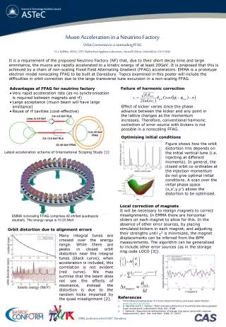
Japanese scheme • Scaling FFAG • Acceleration with a bucket of low frequency RF, 5~20 MHz
Acceleration • No time to modulate RF frequency. • 1 MV/m (ave.) RF voltage gives large longitudinal acceptance. • From 10 to 20 GeV/c within 12 turns.
Accelerator chain • Before acceleration • Target and drift • No cooling section • Four scaling FFAGs, • 0.3 - 1.0 GeV • 1.0 - 3.0 GeV • 3.0 - 10.0 GeV • 10. - 20. Gev • If physics demands, another FFAG • 20. - 50. GeV
Longitudinal emittance vs acceptance(after target and drift) Acceptance of US scheme is 0.167 eV.sec (150 mm). Difference comes from frequency of RF (5 vs. 201 MHz).
Transverse emittance ~100 mm (100,000 pi mm-mrad)