Download
1 / 29
290 likes | 418 Views
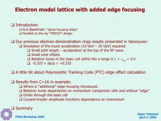
Electron model lattice with added edge focusing. Introduction: Rick Baartman : “Spiral focusing slides” Parallels to the my ‘TRIPLET’ design Our previous electron demonstration rings results presented in Vancouver: Simulation of the muon acceleration (10 GeV – 20 GeV) required:

E N D
Electron model lattice with added edge focusing • Introduction: • Rick Baartman: “Spiral focusing slides” • Parallels to the my ‘TRIPLET’ design • Our previous electron demonstration rings results presented in Vancouver: • Simulation of the muon acceleration (10 GeV – 20 GeV) required: • Small path length – acceleration at the top of the RF wave • Small orbit offsets • Betatron tunes in the basic cell within the a range 0.1 < nx,y < 0.4 • -0.333 < dp/p < +0.333 • A little bit about Polymorphic Tracking Code (PTC) edge effect calculation • Results from C=16 m example: • Where is “additional” edge focusing introduced. • Betatron tunes dependence on momentum comparison with and without “edge” • Orbits through the basic cell • Courant-Snyder amplitude functions dependence on momentum • Summary Dejan Trbojevic April 3, 2005 FFAG Workshop 2005
Slides from the Rick Baartman presentation: ‘Cyclotrons: Classic to FFAG’ - 2002 Thomas focusing and later the Okhawa-Symon-Kolomenski FFAG Dejan Trbojevic April 3, 2005 FFAG Workshop 2005
Slides from the Rick Baartman presentation: In 1954, Kerst realized that the sectors need not be symmetric.By tilting the edges, the one edge became more focusing and theother edge less. But by the strong focusing principle (larger betatron amplitudes in focusing, smaller in defocusing), one could gain nevertheless. This had the important advantage that reverse bends would not be needed (reverse bends made the machine excessively large). (Figure is from J.R. Richardson notes.) The resulting machines no longer had alternating gradients, but Kerst and Symon called them FFAGs anyway. Dejan Trbojevic April 3, 2005 FFAG Workshop 2005
Slides from the Rick Baartman presentation: Dejan Trbojevic April 3, 2005 FFAG Workshop 2005
Slides from the Rick Baartman presentation: Dejan Trbojevic April 3, 2005 FFAG Workshop 2005
Sector Bend with two edges Dejan Trbojevic April 3, 2005 FFAG Workshop 2005
2.Our previous electron demonstration rings results presented in Vancouver • E. D. Courant and D. Trbojevic • Lattice Properties: • Dimensions and lattice functions for the central energy Eo=15 MeV: • Circumference C and number of periods N: • C = 13 m with N = 32 , • C = 13 m with N = 34, • C = 16 m with N = 45, • C = 17 m with N = 45. • Gradients and bending fields/angles. • Momentum Dependence: • Path length per unit cell and for a total length vs. momentum. • Orbit offsets vs. momentum. • tunes vs. momentum. • Amplitude and dispersion functions vs. momentum. Dejan Trbojevic April 3, 2005 FFAG Workshop 2005
Dejan Trbojevic April 3, 2005 FFAG Workshop 2005
Dejan Trbojevic April 3, 2005 FFAG Workshop 2005
GRADIENTS: GF = 7.06035 T/m GD = - 4.59590 T/m Dimensions: LBD = 10 cm LQF = 3.8 cm CAV = 10.6 cm Drift = 3.12 cm Bending Fields: ByQD = 0.1093 T ByQF = - 0.0520 T Bending angles: ANGQD = 0.2186575 ANGQF = -0.039516 q2/q1 = 0.180 Dejan Trbojevic April 3, 2005 FFAG Workshop 2005
Dejan Trbojevic April 3, 2005 FFAG Workshop 2005
A little bit about Polymorphic Tracking Code (PTC) edge effect calculation Dejan Trbojevic April 3, 2005 FFAG Workshop 2005
Dejan Trbojevic April 3, 2005 FFAG Workshop 2005
Dejan Trbojevic April 3, 2005 FFAG Workshop 2005
Dejan Trbojevic April 3, 2005 FFAG Workshop 2005
Dejan Trbojevic April 3, 2005 FFAG Workshop 2005
Dejan Trbojevic April 3, 2005 FFAG Workshop 2005
Dejan Trbojevic April 3, 2005 FFAG Workshop 2005
Dejan Trbojevic April 3, 2005 FFAG Workshop 2005
e Dejan Trbojevic April 3, 2005 FFAG Workshop 2005
Results from C=16 m example: Orbits along the cell at different momenta 19.6 mm dp/p=+44% 5.9 mm dp/p = -44% Dejan Trbojevic April 3, 2005 FFAG Workshop 2005
Results from C=16 m example: Dejan Trbojevic April 3, 2005 FFAG Workshop 2005
Results from C=16 m example: Dejan Trbojevic April 3, 2005 FFAG Workshop 2005
Dejan Trbojevic April 3, 2005 FFAG Workshop 2005
Summary: • A simple straight edge effect application to the ends of the magnets improved the tune dependence on momentum especially in the vertical plane. • Improvements with the curved edges should not be taken seriously because of the very small sizes of the non-scaling FFAG magnets. This approach does improve performance of the scaling FFAG, as Rick Bartmaan had previously explained. Dejan Trbojevic April 3, 2005 FFAG Workshop 2005
Dejan Trbojevic April 3, 2005 FFAG Workshop 2005
15m ring Gun Linac
Dejan Trbojevic April 3, 2005 FFAG Workshop 2005
Dejan Trbojevic April 3, 2005 FFAG Workshop 2005