Download
1 / 69
700 likes | 997 Views
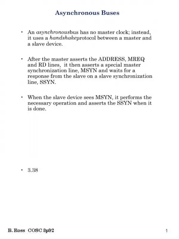
3. Buses. Introduction Electrical Considerations Data Transfer Synchronization Bus Arbitration VME Bus Local Buses PCI Bus PCI Bus Variants Serial Buses. Local Buses (1). Most of the integrated I/O subsystems are connected to the expansion bus Graphics and video adapters

E N D
3. Buses • Introduction • Electrical Considerations • Data Transfer Synchronization • Bus Arbitration • VME Bus • Local Buses • PCI Bus • PCI Bus Variants • Serial Buses Input/Output Systems and Peripheral Devices (03-2)
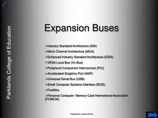
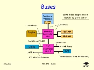
Local Buses (1) • Most of the integrated I/O subsystems are connected to the expansion bus • Graphics and video adapters • SCSI adapters • Network adapters • Currently, many subsystems are integrated onto the system board • Most of the subsystems are connected to the X-bus(utility bus) Input/Output Systems and Peripheral Devices (03-2)
Local Buses (2) Input/Output Systems and Peripheral Devices (03-2)
Local Buses (3) • An I/O module may be connected to the processor’s local bus instead of the expansion bus • The I/O module is redesigned • Methods for connecting to the processor’s local bus: • Direct connection • Buffered connection • Workstation connection Input/Output Systems and Peripheral Devices (03-2)
Local Buses (4) • Direct connection • The module must be redesigned in order to be used with next-generation processors • A single module may be connected to the local bus • Buffered connection • Up to three modules can be connected to the buffered local bus • The processor and a local bus master module may not use the bus simultaneously Input/Output Systems and Peripheral Devices (03-2)
Local Buses (5) • Workstation connection • The processor’s L2 (L3) cache memory controller is combined with a bridge circuit • Provides the interface between the processor, main memory and an I/O bus • The processor can communicate with its cache memories while an I/O module accesses the main memory • The interface of modules connected to the I/O bus is independent of the processor bus Input/Output Systems and Peripheral Devices (03-2)
3. Buses • Introduction • Electrical Considerations • Data Transfer Synchronization • Bus Arbitration • VME Bus • Local Buses • PCI Bus • PCI Bus Variants • Serial Buses Input/Output Systems and Peripheral Devices (03-2)
PCI Bus • PCI Bus • Overview • Operation Details • Bus Arbitration • PCI Transactions • PCI Interrupts Input/Output Systems and Peripheral Devices (03-2)
Overview (1) • PCI - Peripheral Component Interconnect • Developed by Intel • Initial intention:standard for interconnecting the fast circuits on the motherboard not an expansion bus • First version (1.0) – released in 1992 • Defined mandatory design rules • Signals and connections were not defined • Later on, detailed electrical and functional specifications have been defined for the bus Input/Output Systems and Peripheral Devices (03-2)
Overview (2) • Version 2.0 (1993): • 33 MHz, up to 132 MB/s (typically: 80 MB/s) • Version 2.1 (1995) • Version 2.2 (1998) • Version 2.3 (2002) • Version 3.0 (2003) • Optional extensions(starting with vers. 2.1) • 64 bits or 66 MHz: up to 264 MB/s • 64 bits and 66 MHz: up to 528 MB/s Input/Output Systems and Peripheral Devices (03-2)
Overview (3) • The PCI specifications are updated by the PCI Special Interest Group(PCI-SIG), www.pcisig.com • Buffered or workstation connection to the processor’s local bus • The PCI bus is not specific to Intel processors • The specifications impose a limit of 10 electrical loads (3 expansion boards) • Can be extended with PCI-to-PCI bridges Input/Output Systems and Peripheral Devices (03-2)
Overview (4) Input/Output Systems and Peripheral Devices (03-2)
Overview (5) • The bus extensions define a connector family • For 32-bit and 64-bit buses • For 5-V and 3.3-V adapters • Expansion boards are provided with keys • Universal boards • Operate at 5 V or 3.3 V • Can be installed in either type of connector • Version 3.0: allows only motherboard connectors of 3.3 V Input/Output Systems and Peripheral Devices (03-2)
Overview (6) • PCI expansion boards are configured automatically for bus transactions • No manual settings are required • PCI devices implement a set of configuration registers(64 x 32 bits) • The registers contain information about: presence of the device; device type; address space required • The software configures the device’s memory and I/O address decoders Input/Output Systems and Peripheral Devices (03-2)
PCI Bus • PCI Bus • Overview • Operation Details • Bus Arbitration • PCI Transactions • PCI Interrupts Input/Output Systems and Peripheral Devices (03-2)
Operation Details (1) • Synchronous operation • Data integrity is maintained at frequencies down to 0 Hz standby or suspend modes • Transactions are between a master (initiator) and a slave (target) device • Multiplexed address and data signals, AD • Cycle 1: the address is placed onto the bus • Cycle 2: the initiator releases the bus • Cycle 3: the data are placed onto the bus Input/Output Systems and Peripheral Devices (03-2)
Operation Details (2) • If the target is not able to respond in three cycles, it can insert wait states • Three flow-control signals • IRDY# (Initiator Ready): an initiator is ready to accept data (read) or is driving valid data (write) • TRDY# (Target Ready): a target is driving valid data (read) or is ready to accept data • STOP# (Stop): asserted by a target to abort the transaction in progress Input/Output Systems and Peripheral Devices (03-2)
Operation Details (3) • Not all 32 (or 64) bits of the data lines need to be used • C/BE0#..C/BE3# (Command/Byte Enable): indicate which bytes contain valid data • C/BE4#..C/BE7# for 64-bit buses • During cycle 1, the C/BE# signals contain the bus command, e.g.: • I/O Read, I/O Write • Memory Read, Memory Write • Configuration Read, Configuration Write Input/Output Systems and Peripheral Devices (03-2)
Operation Details (4) • The PCI bus does not need terminators • Signal reflections do occur • Signal reflections are used as an advantage • To assert a signal, a device drives the signal line only to half its required level • The signal is reflected back and doubled up to the required activation voltage • Advantages: reduced current; reduced driver size Input/Output Systems and Peripheral Devices (03-2)
PCI Bus • PCI Bus • Overview • Operation Details • Bus Arbitration • PCI Transactions • PCI Interrupts Input/Output Systems and Peripheral Devices (03-2)
Bus Arbitration (1) • An initiator must request to use the bus • A centralized bus arbitration is used • The arbiter is integrated into the chipset • Each PCI initiator has two arbitration lines (REQ#, GNT#) connected to the arbiter • To request the bus, a PCI initiator asserts its REQ# signal • To grant control of the bus, the arbiter asserts the GNT# signal specific to the requesting device Input/Output Systems and Peripheral Devices (03-2)
Bus Arbitration (2) • Arbitration takes place while another initiator controls the bus hidden arbitration • The bus is granted for one transaction • After receiving a grant, the initiator must wait until the current transaction completes • FRAME# and IRDY# are both de-asserted • The PCI specification does not define the arbitration algorithm used by the arbiter Input/Output Systems and Peripheral Devices (03-2)
PCI Bus • PCI Bus • Overview • Operation Details • Bus Arbitration • PCI Transactions • PCI Interrupts Input/Output Systems and Peripheral Devices (03-2)
PCI Transactions (1) • Transactions consist of an address phase followed by one or more data phases • With 64-bit addressing, there are two address phases • Address phase (one clock cycle): • The initiator identifies the target device (AD) and the type of transaction (C/BE#) • The FRAME# signal indicates a valid start address and transaction type Input/Output Systems and Peripheral Devices (03-2)
PCI Transactions (2) • The DEVSEL# signal is asserted by the target to indicate that it has detected its address and is prepared for the transaction • Data phase • A number of data bytes are transferred between the initiator and the target • The FRAME# signal remains asserted until the final data phase • The last data phase is indicated by de-asserting FRAME# and asserting IRDY# Input/Output Systems and Peripheral Devices (03-2)
PCI Transactions (3) Input/Output Systems and Peripheral Devices (03-2)
PCI Transactions (4) • Most PCI transactions are performed in burst mode • A burst transfer consists of: • A single address phase • Multiple data phases • Bus arbitration must be performed only once • The target device latches the start address and increments it in each data phase • The transfer continues as long as FRAME# remains asserted Input/Output Systems and Peripheral Devices (03-2)
PCI Bus • PCI Bus • Overview • Operation Details • Bus Arbitration • PCI Transactions • PCI Interrupts Input/Output Systems and Peripheral Devices (03-2)
PCI Interrupts (1) • The PCI bus provides four level-sensitive interrupt request lines, INTA# .. INTD# • A single-function device must use INTA# • PCI interrupt request lines are shareable • The lines are open-drain • Multiple devices connected to the same line can assert it simultaneously • A particular pattern on the C/BE# lines indicates an interrupt acknowledge cycle Input/Output Systems and Peripheral Devices (03-2)
PCI Interrupts (2) • Interrupt routing • Connecting the device’s PCI INTx# line to a system IRQ line • Interrupt routing should be programmable by the software • The PCI configuration registers store information about the interrupts • Interrupt pinregister the interrupt request line that is used by the device • Interrupt lineregister interrupt routing Input/Output Systems and Peripheral Devices (03-2)
3. Buses • Introduction • Electrical Considerations • Data Transfer Synchronization • Bus Arbitration • VME Bus • Local Buses • PCI Bus • PCI Bus Variants • Serial Buses Input/Output Systems and Peripheral Devices (03-2)
PCI Bus Variants • PCI Bus Variants • PCI-X Bus • PCI Express Bus • Variants for Portable Computers • Variants for Industrial Systems Input/Output Systems and Peripheral Devices (03-2)
PCI-X Bus (1) • Higher-performance extension of the conventional PCI bus • Compatible with diverse variants of the PCI bus • Ensures the transfer rates required for connections such as Gigabit Ethernet, Fiber Channel, and Ultra-640 SCSI • Initially used for servers and workstations Input/Output Systems and Peripheral Devices (03-2)
PCI-X Bus (2) • Version 1.0 • Frequencies up to 133 MHz • 32 or 64 bits • Maximum rate: 1.064 GB/s • Improvements of the conventional protocol: • Split transactions: allow an initiator to make a request for a transfer and then to release the bus Input/Output Systems and Peripheral Devices (03-2)
PCI-X Bus (3) • Byte count: an initiator may specify in advance the number of bytes requested the speculative pre-fetches are eliminated • Hardware compatibility with the previous versions: operation at 33 or 66 MHz, with the conventional protocol • Software compatibilitywith the previous versions: at the OS, BIOS, and device driver levels • Do not require changes Input/Output Systems and Peripheral Devices (03-2)
PCI-X Bus (4) • Version 2.0 • Improvements that allow servers to use I/O technologies with very high performances • 10-Gbits/s Ethernet network • 10-Gbits/sFiber Channel bus • InfiniBand bus • Hardwareand software compatibilityis maintained with the previous generations of the bus Input/Output Systems and Peripheral Devices (03-2)
PCI-X Bus (5) • Higher operating frequencies • PCI-X 266 (DDR – Double Data Rate): 266 MHz, max. 2.128 GB/s • PCI-X 533 (QDR – Quad Data Rate): 533 MHz, max. 4.256 GB/s • PCI-X 1066: 1066 MHz, max. 8.5 GB/s • Maximum performance is 64 times higher compared to the first PCI generation • The PCI-X 133 and later variants allow to use a single connector, one electrical load point-to-point applications Input/Output Systems and Peripheral Devices (03-2)
PCI-X Bus (6) • New features: • ECC (Error Correcting Code): allows to correct one-bit errors • Improved protocol: increases the bus utilization and bus efficiency • Strobe signals (PCI-X 266 and PCI-X 533): drive the clock inputs of data buffers • 1.5-V signals: allow operation at higher frequencies Input/Output Systems and Peripheral Devices (03-2)
PCI Bus Variants • PCI Bus Variants • PCI-X Bus • PCI Express Bus • Variants for Portable Computers • Variants for Industrial Systems Input/Output Systems and Peripheral Devices (03-2)
PCI Express Bus • PCI Express Bus • Overview • PCI Express Link • Bus Topology • Architecture Layers • PCI Express Transactions • PCI Express Interrupts • Versions of PCI Express Standards Input/Output Systems and Peripheral Devices (03-2)
Overview (1) • PCI-E, PCIe • Originates from preliminary specifications of the 3GIO (Third Generation I/O) interface • Later on, the specifications have been transferred to the PCI Special Interest Group • Serial Bus • Advantages: reduced board complexity, lower pin count, lower cost Input/Output Systems and Peripheral Devices (03-2)
Overview (2) • Allows interconnections between integrated circuits and boards through connectors • Unifies the I/O architecture for various types of systems: desktop, portable, server, embedded computers • Software model compatible with conventional PCI architecture does not require changes of the OS and drivers Input/Output Systems and Peripheral Devices (03-2)
Overview (3) • Retains the advantageous features of the previous PCI buses: • Same communication model • Same address spaces • Same transaction types • Introduces various improvements: • Serial connection: eliminates the disadvantages of parallel buses difficulty of synchronization • Point-to-point connection Input/Output Systems and Peripheral Devices (03-2)
Overview (4) • Packet-based protocol • Scalable performance variable number of communication lanes • Quality of Service (QoS) feature differentiated performance • Advanced power management • Advanced error reporting and handling • Possibility of connecting and disconnecting the peripheral devices during operation Input/Output Systems and Peripheral Devices (03-2)
PCI Express Bus • PCI Express Bus • Overview • PCI Express Link • Bus Topology • Architecture Layers • PCI Express Transactions • PCI Express Interrupts • Versions of PCI Express Standards Input/Output Systems and Peripheral Devices (03-2)
PCI Express Link (1) • Minimal PCIe link: two unidirectional communication channels • Packets are transmitted: data, commands • Channel: two wires with differential signals • Communication lane • PCIe link with multiple communication lanes: xN • Link width and frequency of operation: set automatically Input/Output Systems and Peripheral Devices (03-2)
PCI Express Link (2) • Operating frequencies: • 2.5 GHz (2.5 Gbits/s for each direction) • 5 GHz • 8 GHz Input/Output Systems and Peripheral Devices (03-2)
PCI Express Bus • PCI Express Bus • Overview • PCI Express Link • Bus Topology • Architecture Layers • PCI Express Transactions • PCI Express Interrupts • Versions of PCI Express Standards Input/Output Systems and Peripheral Devices (03-2)
Bus Topology (1) • Root complex defines a hierarchy • Connects the CPU and memory to peripherals • PCIe ports: each defines a hierarchy domain • Endpoints • Peripheral devices: initiators (requesters), targets (completers) • Up to 8 logical functions (0 .. 7) • Switch • Replaces the shared bus • Enables direct communication between two devices Input/Output Systems and Peripheral Devices (03-2)
Bus Topology (2) Input/Output Systems and Peripheral Devices (03-2)