Download
1 / 23
300 likes | 525 Views
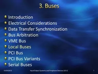
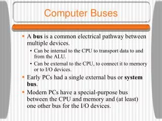
Buses. Some slides adapted from lecture by David Culler. Pentium 4 Processor. L1 and L2 caches. 3.2 GB/sec. > 100 MB/sec. Memory Controller Hub. RDRAM. Display. RDRAM. Dual Ultra ATA/100. 24 Mbit/sec. I/O Controller Hub 2. Disks. 4 USB Ports. PCI. LAN.

E N D
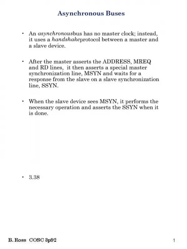
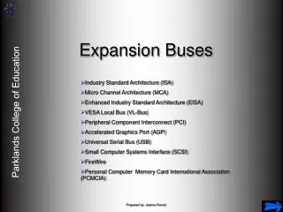
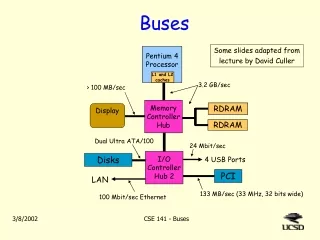
Buses Some slides adapted from lecture by David Culler Pentium 4 Processor L1 and L2 caches 3.2 GB/sec > 100 MB/sec Memory Controller Hub RDRAM Display RDRAM Dual Ultra ATA/100 24 Mbit/sec I/O Controller Hub 2 Disks 4 USB Ports PCI LAN 133 MB/sec (33 MHz, 32 bits wide) 100 Mbit/sec Ethernet CSE 141 - Buses
Processor Input Control Memory Datapath Output What is a bus? • A shared communication link • A single set of wires (aka lines) used to connect two or more components • Unlike a typical wire in a processor, a bus can communicate in different directions at different times. CSE 141 - Buses
Memory Processor Advantages of Buses • Versatility: • New devices can be added easily • Peripheral devices can be moved between computersystems that use the same bus standard • Low Cost: • A single set of wires is shared in multiple ways • Provides a way to manage the complexity of design • Device only has to implement the bus standard. I/O Device I/O Device I/O Device CSE 141 - Buses
Memory Processor Disadvantage of Buses • It creates a communication bottleneck • Bus bandwidth can limit the maximum I/O throughput • The maximum bus speed is largely limited by: • The length of the bus • The number of devices on the bus • The need to support a range of devices with: • Widely varying latencies • Widely varying data transfer rates I/O Device I/O Device I/O Device CSE 141 - Buses
The General Organization of a Bus Control Lines • Control lines: • Signal requests and acknowledgments • Indicate what type of information is on the data lines, if there are errors, etc. • Data linescarry information between the source and the destination: • Data • Addresses • Complex commands Data Lines CSE 141 - Buses
Typical bus transaction 1. Various components request access to bus 2. One is selected (it becomes the bus master for this transaction) 3. The master puts an address and request type (e.g. read or write) on the bus 4. The master and the addressed component (slave) send data one way or the other (depending on request type) 5. The bus master signals that it’s done. Return to step 1 Master issues command Bus Master Bus Slave Data can go either way CSE 141 - Buses
Types of buses • Processor – memory bus very short (a few inches) • usually designed for specific processor. • highest bandwidth, lowest latency • optimized for cache block transfers • Backplane bus up to about 20 inches long • backplane = an interconnection structure within the chassis • connects proc&memory to nearby components (multimedia accelerators, network cards, I/O adaptors, ...) • standardized, allowing multiple vendors of devices • I/O buses longer, lower bandwidth, higher latency • connect to other devices (disk, printer, other computers ...) • need to match a wide range of I/O devices • connects to the processor-memory bus or backplane bus CSE 141 - Buses
System with only one bus • A single bus (the backplane bus) is used for: • Processor to memory communication • Communication between I/O devices and memory • Advantages: Simple and low cost • Disadvantage: slow - the bus is a major bottleneck • Example: IBM PC – AT (ancient history) Backplane Bus Processor Memory I/O Devices CSE 141 - Buses
A Two-Bus System Processor Memory Bus • I/O buses tap into the processor-memory bus via bus adaptors: • Processor-memory bus: mainly for processor-memory traffic • I/O buses: provide expansion slots for I/O devices Processor Memory Bus Adaptor Bus Adaptor Bus Adaptor I/O Bus I/O Bus I/O Bus CSE 141 - Buses
Bus Adaptor Bus Adaptor A Three-Bus System Processor Memory Bus • Backplane bus taps into the processor-memory bus • I/O buses are connected to the backplane bus • Advantage: much less load on the processor bus. Processor Memory Bus Adaptor I/O Bus Backplane Bus I/O Bus CSE 141 - Buses
Example: Pentium 4 system Pentium 4 Processor L1 and L2 caches 3.2 GB/sec > 100 MB/sec Memory Controller Hub RDRAM Display RDRAM Dual Ultra ATA/100 24 Mbit/sec I/O Controller Hub 2 Disks 4 USB Ports PCI LAN 133 MB/sec (33 MHz, 32 bits wide) 100 Mbit/sec Ethernet CSE 141 - Buses
Synchronous vs Asynchronous Bus • Synchronous Bus: • Control and data signals move with respect to a common clock (usually one of the bus control lines) • Advantage: low latency & high bandwidth. • Disadvantages: • Every device on the bus must run at the same clock rate • To avoid clock skew, bus cannot be long if it is fast • Asynchronous Bus: • It is not clocked • It can accommodate a wide range of devices • It can be lengthened without worrying about clock skew • Communication protocol is more complicated CSE 141 - Buses
Typical asynchronous bus protocol • Sender puts data on data lines, sets a control line to mean “Hey! I put some data on the line” • Receiver sees the control lines, reads the data, then sets a different line to mean “OK, I got it. You can move on to the next settings.” • Sender turns off its data and control lines. • Receiver turns off it’s acknowledgement control line. We are now ready for the next transaction. Why does sender need to wait for step 4?? CSE 141 - Buses
Synchronous bus example: the PCI bus • PCI = Peripheral Component Interconnection • Introduced by Intel in early 90’s • Adapted as industry standard – used in PC’s, Mac’s, etc • Initially 33 MHz, improved to 66. PCI-X is 133 MHz. • Two widths: 32 or 64 data lines. • 32 bits wide, 66 MHz 266 MByte/sec peak bw • Write protocol: • master component puts address on bus (1 cycle) • then sends data for 0 to many cycles • Read protocol: • master component puts address on bus, then 1 idle cycle • responding component puts data on bus for 0 to many cycles CSE 141 - Buses
The PCI standard (No, you don’t need to know this – but it may help understand what PCI is.) The 32-bit PCI standard specifies a 62-pin connection: 32 data lines (used both for address and data) 4 Command/Byte Enable lines 2 “Wait” lines (one each way) – “Hold up a moment!” 2 “Stop” lines (one each way) – “I’m finished!” 2 lines for Request and Grant (we’ll get to in a moment) Assorted other required control signals, e.g. clock, reset, parity, 2 error lines, ... And a bunch of optional control lines for interrupts, cache control, etc. CSE 141 - Buses
Buses so far ... Master Slave Bus Master: has ability to control the bus, initiates transaction Bus Slave: module activated by the transaction Bus Communication Protocol: specification of sequence of events and timing requirements in transferring information. Asynchronous Bus Transfers: control lines (req, ack) serve to orchestrate sequencing. Synchronous Bus Transfers: sequence relative to common clock. ° ° ° Control Lines Address Lines Data Lines CSE 141 - Buses
Choosing a master How do you decide which component will be the bus master - the one that initiates a bus transaction? • The simplest solution: • The processor is the only bus master • Major drawback: the processor is involved in every transaction. • Multiple masters: • A bus master wanting to use the bus makes a request • It cannot use the bus until its request is granted • It must release the bus when it’s finished PCI bus (and others) use “request” and “grant” signals CSE 141 - Buses
Bus arbitration: choosing a master • Bus arbitration schemes must to balance 2 factors: • Bus priority: highest priority device should be serviced first • Fairness: even the lowest priority device should never be completely locked out from the bus • Bus arbitration schemes can be divided into four broad classes: • Daisy chain arbitration • Centralized arbitration • Distributed arbitration by self-selection: • each device wanting the bus places an id code on the bus. • they all follow the same protocol to choose master • Distributed arbitration by collision detection (e.g. Ethernet) CSE 141 - Buses
Daisy Chain Bus Arbitration • Advantage: simple • Disadvantages: • Doesn’t assure fairness: A low-priority device may be locked out indefinitely • The daisy chain grant signal also limits the bus speed Device 1 Highest Priority Device N Lowest Priority Device 2 Grant Grant Grant Release Bus Arbiter Request wired-OR CSE 141 - Buses
Centralized Arbitration • Used in essentially all processor-memory busses and in high-speed I/O busses Device 1 Device N Device 2 Req Grant Bus Arbiter CSE 141 - Buses
Increasing the Bus Bandwidth • Use separate address lines and data lines: • Address and data can be transmitted in one bus cycle • Cost: more bus lines • Increase bus width: • By increasing the width of the data bus, transfers of multiple words require fewer bus cycles • Example: SPARCstation 20’s memory bus is 128 bit wide • Cost: more bus lines • Block transfers: • Allow the bus to transfer multiple words in back-to-back bus cycles • Only one address needs to be sent at the beginning • Bus isn’t released until the last word is transferred • Cost: (a) increased complexity (b) decreased response time for request CSE 141 - Buses
Summary of Bus Options Option High performance Low cost • Bus width Separate address Multiplex address & data lines & data lines • Data width Wider is faster Narrower is cheaper (e.g., 32 bits) (e.g., 8 bits) • Transfer size Multiple words has Single-word transfer less bus overhead is simpler • Bus masters Multiple Single master (requires arbitration) (no arbitration) • Clocking Synchronous Asynchronous • Protocol Pipelined Serial CSE 141 - Buses
Computer of the day • Sony PlayStation 2 (from www.arstechnica.com/reviews/1q00/playstation2ee-1.html) • MIPS III core (2 issue with 128-bit multimedia insts) plus: • Two vector units (VU), each of which can issue 2 instructions per cycle, one of which can be a 4-way SIMD instruction. Thus, each VU can issue four 32-bit Float Multiply-Adds instructions/cycle plus one more instruction. • PS2 can do about 10 fma’s and 4 float divides per cycle • At 250MHz, that’s 6 GFLOP/sec • DMA controller can handle 10 simultaneous transactions (e.g. to sound chip, graphics engine). • Lots of buses, special caches, MPEG-2 decoder, etc • PS2 also has Graphics, Sound, and I/O processors. • You ain’t seen nothing yet! • PS3 (expected 2004-5) should be a 1 TFLOP/sec machine! • If FLOP/sec were everything, that would be almost as fast as SDSC’s Blue Horizon, for 1/10,000 the cost! CSE 141 - Buses