Download

1 / 28
280 likes | 412 Views
The ESA MUSIC Project Breadboard HW Partitioning and ASIC Design. Advanced Mobile Satellite Systems & Technologies presentation days ESA./ESTEC – 14-15 November 2000. Outline. MUSIC Receiver Implementation MUSIC RX FPGA Complexity FPGA Design Flow HW/SW Partitioning EC-BAID ASIC

E N D
The ESA MUSICProjectBreadboard HW Partitioning and ASIC Design Advanced Mobile Satellite Systems & Technologies presentation days ESA./ESTEC – 14-15 November 2000
Outline • MUSIC Receiver Implementation • MUSIC RX FPGA Complexity • FPGA Design Flow • HW/SW Partitioning • EC-BAID ASIC • ASIC Design Flow • ASIC Architecture • ASIC Features
In-Phase P Interface Front-End CIC Decimation n =4 n =2 s s BER SNIR Prompt-I R c f r f f =4R 2R f s d d c c s 2 N-stage BER N-stage Compensation SNIR Interp. R Comb E/L-I Measurem. Integrator Filter / CMF c Estimation R s Symbol Demux-I Start f s f s Code I epoch I/Q Soft f =4.464 MHz Data IF Input IFd L R s DCO EC-BAID ADC CCAU ˆ Unit Q Symb. Clock f =70 MHz Int. Clock 8R Quadrature IF c Front-End CIC Decimation n n =4 s f s s Signal Detect / R c Prompt-Q Demod. Enable r f f f =4R 2R f s d d c s 2 N-stage N-stage Compensation R Interp. c E/L-Q Integrator Comb Filter / CMF R Demux-Q c R s Sync I/Q CCTU AGC Correlator E/L AFC Loop FED Filter Pilot Channel Code Traffic Channel Code D f MUSIC RX Functional Block Diagram
ST 18952 DSP In-Phase P Interface Front-End CIC Decimation n =4 n =2 s s BER SNIR Prompt-I R c f r f f =4R 2R f s d d c c s 2 N-stage BER N-stage Compensation SNIR Interp. R Comb E/L-I Measurem. Integrator Filter / CMF c Estimation R s Symbol Demux-I Start f s f s Code I epoch I/Q Soft f =4.464 MHz Data IF Input IFd L R s DCO EC-BAID ADC CCAU ˆ Unit Q Symb. ASIC Clock f =70 MHz Int. Clock 8R Quadrature IF c Front-End AD S807 CIC Decimation n n =4 s f s s Signal Detect / R c Prompt-Q Demod. Enable r f f f =4R 2R f s d d c s 2 N-stage N-stage Compensation R Interp. c E/L-Q Integrator Comb Filter / CMF R Demux-Q c R s Sync I/Q CCTU AGC Correlator E/L AFC Loop FED Filter Pilot Channel Code Traffic Channel Code FPGAs - ALTERA 10K100 D f MUSIC RX Implementation
In-Phase P Interface Front-End CIC Decimation n =4 n =2 s s BER SNIR Prompt-I R c f r f f =4R 2R f s d d c c s 2 N-stage BER N-stage Compensation SNIR Interp. R Comb E/L-I Measurem. Integrator Filter / CMF c Estimation R s Symbol Demux-I Start f s f s Code I epoch I/Q Soft f =4.464 MHz Data IF Input IFd L R s DCO EC-BAID ADC CCAU ˆ Unit Q Symb. Clock f =70 MHz Int. Clock 8R Quadrature IF c Front-End CIC Decimation n n =4 s f s s Signal Detect / R c Prompt-Q Demod. Enable r f f f =4R 2R f s d d c s 2 N-stage N-stage Compensation R Interp. c E/L-Q Integrator Comb Filter / CMF R Demux-Q c R s Sync I/Q CCTU AGC Correlator E/L AFC Loop FED Filter Pilot Channel Code Traffic Channel Code D f MUSIC RX Implementation (Intermediate) ST 18952 DSP AD S807 FPGAs - ALTERA 10K100
MUSIC RX FPGA Design Flow Requirement VHDL RTL Model Synthesis Constraints FORTRAN Floating Point Model Logic Synthesis ALTERA Library no FORTRAN Simulation OK? FORTRAN Test Bench yes no VHDL FPGA Gate Level Netlist OK? yes VHDL Test Bench VHDL Gate Level Simulation FORTRAN Bit True Model ALTERA Library no OK? FORTRAN Simulation yes Device Fitting no OK? VHDL FPGA Gate Level Netlist yes Macro Cell (RAM, ROM) VHDL Model VHDL RTL Model VHDL Test Bench VHDL Gate Level Simulation ALTERA Library VHDL Simulation VHDL Test Bench no OK? Interconnection Delay no yes OK? yes Device Programming
In-Phase P Interface Front-End CIC Decimation n =4 n =2 s s BER SNIR Prompt-I R c f r f f =4R 2R f s d d c c s 2 N-stage BER N-stage Compensation SNIR Interp. R Comb E/L-I Measurem. Integrator Filter / CMF c Estimation R s Symbol Demux-I Start f s f s Code I epoch I/Q Soft f =4.464 MHz Data IF Input IFd L R s DCO EC-BAID ADC CCAU ˆ Unit Q Symb. Clock f =70 MHz Int. Clock 8R Quadrature IF c Front-End CIC Decimation n n =4 s f s s Signal Detect / R c Prompt-Q Demod. Enable r f f f =4R 2R f s d d c s 2 N-stage N-stage Compensation R Interp. c E/L-Q Integrator Comb Filter / CMF R Demux-Q c R s Sync I/Q CCTU AGC Correlator E/L AFC Loop FED Filter Pilot Channel Code Traffic Channel Code D f MUSIC RX Implementation (Intermediate) ST 18952 DSP 1st 3rd/4th AD S807 2nd FPGAs - ALTERA 10K100
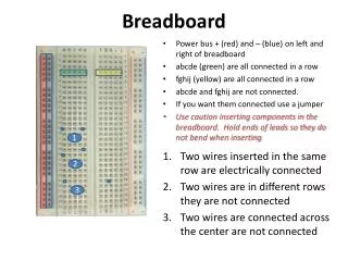
CONNECTION BY FLAT CABLE MUSIC RX Implementation (Intermediate) PROGRAMMING FLAT CABLE PROTEO #2 PROTEO #1 3rd CPLD 4th CPLD 2nd CPLD 1st CPLD
PROTEO #2 4th CPLD 3rd CPLD 2nd CPLD 1st CPLD PROTEO #1
MUSIC RX Implementation (Final) EC-BAID BOARD PROGRAMMING FLAT CABLE PROTEO #1 extra CPLD CONNECTION EC-BAID BY FLAT CABLE EC-BAID ASIC 2nd CPLD 1st CPLD
EC-BAID ASIC Design Flow Requirement VHDL RTL Model Synthesis Constraints FORTRAN Floating Point Model Logic Synthesis ST HCMOS7 Library no FORTRAN Simulation FORTRAN Test Bench OK? yes no OK? VHDL Gate Level Netlist yes VHDL Test Bench FORTRAN Bit True Model VHDL Gate Level Simulation ST HCMOS7 Library no FORTRAN Simulation OK? yes no OK? EC-BAID ASIC Back-End yes VHDL Test Bench Macro Cell (RAM, ROM) VHDL Model VHDL RTL Model VHDL Post-Layout Simulation ST HCMOS7 Library no VHDL Simulation VHDL Test Bench OK? Parasitic Delay yes no OK? EC-BAID ASIC Foundry Run yes
Correlation Receiver y e L å 1/T i s The MUSIC core: EC-BAID 3/3 1/T c 1 1/T s 1/T + c 1/T b b ' c s 1 1 1,i + MUX3 1/T s 3 L å 3/T 3/T c c AGC 1 loop Y RAM mux control MUX2 128 x 42 . 3/T ( )* 3/T c g (1-F) mem control x 3/T n.o. x 1,w c 1,w 3/T - + + c - + + X RAM 384 x 46 1/T c s 1,i 3/T ( ) c n.o. x c · 1,w 1 c 1,i L 3/T c hardware-multiplexing area
EC-BAID Bit-true Simulation • WH=E-GOLD sequences • L=32 • ideal chip timing and carrier frequency/phase recovery • asynchronous MAI with evenly-distributed delays on one symbol period • adaptation step = 2-13 or 2-15 • N=L/2 active users with C/I=-6 dB each
wC wC Shortened Programmable Observation Window Optimization of the EC-BAID: Window Length 1/2 Maximum Observation Window (3L chips) y-1 y0 y1
Optimization of the EC-BAID: Window Length 2/2 Optimum Length: 2 symbol intervals (0.5+1+0.5)
EC-BAID with Leakage Leakage factor Adaptive EC-BAID with Leakage Standard EC-BAID
ST HCMOS7 0.25 m Technology • Key Features • 2.5 V operating voltage, 3.3 V I/O • Gate Density: 35 Kgates/mm2 • 500 MHz systems clock • 6 levels of metal with minimum enclosures, stacked contacts and VIAs • Ultra low power dissipation: 0.1 W/MHz/gate/std load • In production since June 1998
TESTING CONFIG INPUT SYNC. OUTPUT DATA OUTPUT SYNC. MONITOR INPUT DATA EC-BAID ASIC pinout STM & TEAM EC-BAID
EC-BAID ASIC Layout RAM 128 x 43 RAM 384 x 46 2 mm2
EC-BAID ASIC Main Features • Robust Blind Interference Mitigation Detector ASIC • Programmable Code Length: L=32, 64 and 128 • 5 Mchip/sec Maximum Chip Rate • Programmable Convergence Speed • Low complexity: 27 Kgates + 23 Kbit RAM • Low power consumption: 45 mW @ 16 MHz clock - 2 Mchip/s • Reduced I/O pin number: 47 • Embedded Phase Recovery Unit • Switchable on/off • Programmable Loop Filter Parameters (BW and DF) • Programmable Lock Detector • ASIC Design-reuse approach allows for: • re-design to meet other system specification: higher chip rates, different I/O interfaces, etc. • re-targeting to different silicon technologies as ASSP • integration in more complex System-on-Chip design