Download

1 / 16
190 likes | 502 Views
INCOMING PHONE RING LIGHT FLASHER. SUBMITTED BY EDGEFX TEAM. ABSTRACT. A circuit is designed which flashes a light whenever there a call in phone. The circuit uses an Opto -isolator and other basic components to achieve this.

E N D
INCOMING PHONE RING LIGHT FLASHER SUBMITTED BY EDGEFX TEAM
ABSTRACT • A circuit is designed which flashes a light whenever there a call in phone. • The circuit uses an Opto-isolator and other basic components to achieve this. • This system can be very useful in a situation where there is lots of noise and it is impossible to hear the phone, such as a workshop, factory etc.
HARD WARE EQUIPMENTS • POWER SUPPLY BLOCK • RESISTOR • CAPACITOR • OPTO ISOLATOR • TRANSISTOR • RELAY • LOAD • DIODE • ZENER DIODE
EMBEDDED SYSTEMS Definition for :- EMBEDDED SYSTEMS • A combination of hardware and software which together form a component of a larger machine. • An example of an embedded system is a microprocessor that controls an automobile engine. • An embedded system is designed to run on its own without human intervention, and may be required to respond to events in real time.
1N4007 Diodes are used to convert AC into DC these are used as half wave rectifier or full wave rectifier. Three points must he kept in mind while using any type of diode.
The resistor, RS is connected in series with the zener diode to limit the current flow through the diode with the voltage source, VS being connected across the combination. The stabilised output voltage Vout is taken from across the zener diode. The zener diode is connected with its cathode terminal connected to the positive rail of the DC supply so it is reverse biased and will be operating in its breakdown condition.
BC547 • The BC547 transistor is an NPN Epitaxial Silicon Transistor. • The BC547 transistor is a general-purpose transistor in small plastic packages. • It is used in general-purpose switching and amplification BC847/BC547 series 45 V, 100 mA NPN general-purpose transistors. • Whenever base is high, then current starts flowing through base and emitter and after that only current will pass from collector to emitter
MOC3021 ( OPTO COUPLER ) • Opto-couplers are made up of a LED and a light sensitive device, all wrapped up in one package • no electrical connection between the two devices • The light sensitive device may be a photodiode, phototransistor, or more esoteric devices such as thyristors, triacs etc.
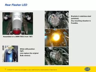
RELAY • IT IS A ELECTRO MAGNETIC SWITCH • USED TO CONTROL THE ELECTRICAL DEVICES • COPPER CORE MAGNETIC FLUX PLAYS MAIN ROLE HERE
LOAD INDUCTIVE LOAD: An inductive load consists of a load created by a wire wound coil, such as in a relay or solenoid, a transformer, or any load which uses a winding over a magnetic iron core. Breaking an inductive load is usually more severe than breaking a resistive load and will generally produce heavy arcing.
BIBILOGRAPHY • www.beyondlogic.org • www.wikipedia.org • www.howstuffworks.com • www.alldatasheets.com