Download
1 / 17
210 likes | 665 Views
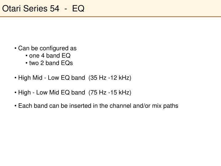
Otari Series 54 - EQ. Can be configured as one 4 band EQ two 2 band EQs High Mid - Low EQ band (35 Hz -12 kHz) High - Low Mid EQ band (75 Hz -15 kHz) Each band can be inserted in the channel and/or mix paths. Otari Series 54 - EQ. “High-Low Mid” (HI LM). 750 Hz-15 kHz.

E N D
Otari Series 54 - EQ • Can be configured as • one 4 band EQ • two 2 band EQs • High Mid - Low EQ band (35 Hz -12 kHz) • High - Low Mid EQ band (75 Hz -15 kHz) • Each band can be inserted in the channel and/or mix paths
Otari Series 54 - EQ “High-Low Mid” (HI LM) 750 Hz-15 kHz “High Mid-Low” (HM LO) 400 Hz-12 kHz 75 Hz-3 kHz 35-700 Hz
Otari Series 54 - EQ Inserts Low-High Mid EQin Channel Path Inserts High-Low Mid EQin Channel Path Default location of each EQ bandis the Mix Path EQ Power OnChannel Path EQ Power OnMix Path
Otari Series 54 - EQ Boost and cut±15 dB3 dB per indent Bandwidth Broad = 2 octavesMedium = 0.5 octaves Narrow = 0.2 octaves Frequency (Hz)
Otari Series 54 - Low Cut Filter Low Cut Filter 18 dB/octave3 dB knee at 40 Hz One filter for each path
Otari Series 54 - Mute Groups Assign the console channelChannel Path to Mute Group A or B Assign the console channelMix Path to Mute Group C or D A and B are Channel Path onlyC and D are Mix Path only
Otari Series 54 - Mute Groups Assign Mute Groups to a specific Mute button Mute buttons e.g., if Mute Group A is assigned to the Mute 4 button, pressing MUTE 4 will mute all channels assigned to Mute Group A
Otari Series 54 - Phase Reversal Phase Reversal (180°)Channel Path Note: these are NOT phase indicator lights Phase Reversal (180°)Mix Path
Otari Series 54 - Signal Presence Peak indicator Signal presence Thresholds set in Central Control panel (leave as VAR) Mix path peak and signal indicators
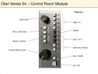
Otari Series 54 - Solo Solo the console channelChannel Path Solo the console channelMix Path
Otari Series 54 - Solo Solo volume control AFL = After Fader Listen PFL = Pre Fader Listen(before fader) Defeats (turns off) anything in Solo Switches betweenAFL and PFL solo listen
Otari Series 54 - Patchbay (Console Channel) Into TAPE Input Source Output of channel Signal out of Tape Machine Into the Tape Machine
Otari Series 54 - Patchbay (Console Channel) External signal(outside of console) Insert Send and Return Line Pre-amp In
Otari Series 54 - Patchbay (Half-Normal) Signal goes from Tape Machine OUT to TAPE Input Source without any cables (“normalled”) What is normalled and signal flow direction is indicated by the arrows
Otari Series 54 - Patchbay (Half Normal) Cable Inserted HereNormal is not broken (signal still goes from Tape Machine OUT into TAPE Input SourceAlso get a copy of the signal (Tape Machine OUT) out of the cable Cable Inserted HereNormal is broken (signal no longer goes from Tape Machine OUT into TAPE Input Source
Otari Series 54 - Patchbay (Mult) Signal patched into one jack is copied and sent out the other three jacks Signal introduced here A copy comes out here