Download
1 / 1
20 likes | 148 Views
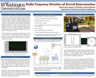
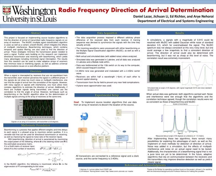
λ/2. λ/2. Tx 2.4G. Rx 2.4G. Rx 2.4G. Rx 2.4G. GPS Disciplined Oscillator. Plane Wave. Radio Frequency Direction of Arrival Determination Daniel Lazar, Jichuan Li, Ed Richter, and Arye Nehorai Department of Electrical and Systems Engineering. Clock Signal. 10MHz Reference. φ.

E N D
λ/2 λ/2 Tx 2.4G Rx 2.4G Rx 2.4G Rx 2.4G GPS Disciplined Oscillator Plane Wave Radio Frequency Direction of Arrival Determination Daniel Lazar, Jichuan Li, Ed Richter, and AryeNehorai Department of Electrical and Systems Engineering Clock Signal 10MHz Reference φ Abstract Data Acquisition Results • The data acquisition process imposed a different arbitrary phase difference of the received data from each receiver. A training sequence was devised to synchronize the signals with the time they actually arrived. • The incoming waveforms were processed with either beamforming or the Multiple Signal Classification algorithm (MuSIC), as well as with a correlation. • Both actual and simulated data (with added noise) where analyzed. • Simulated data was generated in Labview, and all data was analyzed in Labview and a Matlab node within. • Data was bottlenecked at the 1Gb switch on its way to the computer, which caused frequent overflow. • A 20kHz tone was generated and modulated with a 2.4GHz carrier wave. • Receivers are within half a wavelength (~6cm) of each other to prevent spatial aliasing. • Transmission from the far field to prevent any near field complications. • A plane wave approximation was used. This project is focused on implementing source location algorithms to find the direction of arrival of transmitted radio frequency signals on an array of receivers. The MuSIC (multiple signal classification) algorithm is used, as well as a variant, smooth-MuSIC, which mitigates the effects of multipath interference. Beamforming techniques, which combine temporal and spatial filtering, are also used to find the direction of arrival. These strategies minimize the transmission power needed to send a signal. Further work building on this research can implement directional transmission and receiving with beamforming, which yields many advantages including minimized signal interception. The results from this research can be used to make adaptive arrays of receivers that minimize noise or interfering signals, as well as address universal communications issues on a cost-effective platform. In simulations, a signals with a magnitude of 0.015 could be resolved with MuSIC with added Gaussian white noise of standard deviation 0.5, which far overshadowed the signal. The MuSIC spectrum was not always consistent at this very noisy level, but one could average a few snapshots to find a consistent direction of arrival. The direction of arrival could also be determined with beamforming, but it was not as sharp at this level of noise. The correlation result was extremely inconsistent. Overview When a signal is intercepted by receivers that are not equidistant from the transmitter, each receiver perceives the signal in a different phase. If the signals do not show too much noise or multipath interference, one can find the angle of arrival from the correlation of the signals. However, with noisy signals or signals with interference, one must utilize more complex algorithms to estimate the direction of arrival. Additionally, if there are multiple signals being transmitted, one cannot use the correlation to find the angle of arrival. However, techniques such as beamforming or the MuSIC algorithm allow for the determination of multiple signals arriving at the array of receivers at the same time. Simulated data at angle of 45 degrees, with signal magnitude 0.015 and noise standard deviation of 0.5 When actual data was gathered, both algorithms worked well. Noise and interference were low enough that the algorithms and the correlation technique agreed, though the correlation results were not as consistent as those of beamforming and MuSIC Experimental Setup Goal: To implement source location algorithms that use data from an array of receivers to discern the location of the source. Signals on an array of 3 receivers, with transmitter at 30 degrees. Mathematic Foundation Beamforming is a process that applies different weights and time delays to each signal in a phased array to maximize certain qualities. It is a versatile tool that can be used for directional transmission or receiving, as well as improving the signal-to-noise ratio of the receiver inputs. With beamforming, direction of arrival is ascertained by maximizing the output power of the following, where d is the steering vector and Ris the estimated covariance matrix. 1 X is a NxM matrix of reciever input, where N is the number of receivers 2 3 In the MuSIC algorithm, the following is maximized, where Qn is the eigenvectors of R corresponding to the noise: Measured data at angle of 60 degrees at a distance of 1.5 meters. After implementing these two algorithms, there remain many possibilities for exploring the advantages of each, as well as the implement of more methods for detection of direction of arrival. Noise was added in a simulation, but the effects of multipath interference and noise on an actual signal need to be tested. Additionally, the characteristics of a beamforming signal that is not a pure tone are yet to be determined. In the future, adaptive algorithms that rely on communication between the receivers and the transmitters may improve direction detection as well as yield a clearer signal. 1Gb Switch All transceivers are connected to a reference signal and a clock source, and the carrier frequency is 2.4GHz. References and Acknowledgments Thanks to Ed Richter for spending countless hours on this project, Jichuan Li for assisting with the theoretical background and Professor Nehorai for making this possible. 1.Nehorai, A. Lecture slides from CSSIP Lab. 2,3.Professor RavirajAdve’s notes: http://www.comm.utoronto.ca/~rsadve