Download
1 / 18
180 likes | 246 Views
Supported by. Resistive Wall Mode Stabilization of High- b NSTX Plasmas. Columbia U Comp-X General Atomics INEL Johns Hopkins U LANL LLNL Lodestar MIT Nova Photonics NYU ORNL PPPL PSI SNL UC Davis UC Irvine UCLA UCSD U Maryland U New Mexico U Rochester U Washington

E N D
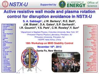
Supported by Resistive Wall Mode Stabilization of High-b NSTX Plasmas Columbia U Comp-X General Atomics INEL Johns Hopkins U LANL LLNL Lodestar MIT Nova Photonics NYU ORNL PPPL PSI SNL UC Davis UC Irvine UCLA UCSD U Maryland U New Mexico U Rochester U Washington U Wisconsin Culham Sci Ctr Hiroshima U HIST Kyushu Tokai U Niigata U Tsukuba U U Tokyo JAERI Ioffe Inst TRINITI KBSI KAIST ENEA, Frascati CEA, Cadarache IPP, Jülich IPP, Garching U Quebec A.C. Sontag1, S. A. Sabbagh1, J.M. Bialek1, D.A. Gates2, A. H. Glasser3, B.P. LeBlanc2, J.E. Menard2, W. Zhu1, M.G. Bell2, R. E. Bell2, A. Bondeson4, J.D. Callen5, M.S. Chu6, C.C. Hegna5, S. M. Kaye2, L. L. Lao6, Y. Liu4, R. Maingi7, D. Mueller2, K.C. Shaing5, D. Stutman8, K. Tritz8 1Department of Applied Physics, Columbia University 2Plasma Physics Laboratory, Princeton University 3Los Alamos National Laboratory 4Institute for Electromagnetic Field Theory, Chalmers U., Goteborg, Sweden 5University of Wisconsin - Madison 6General Atomics 7Oak Ridge National Laboratory 8Johns Hopkins University 46th Annual Meeting of Division of Plasma Physics American Physical Society November 15-19, 2004 Savannah, GA
Understanding of b-Limiting Instabilities Necessary for Sustained High-b Operation • Motivation • Recent machine upgrades have extended performance further into the high-b long-pulse regime • Several instabilities can limit performance in this regime • Resistive wall mode (RWM) can limit high-b operations at low plasma rotation and low-q • Outline • RWM identification at high-b and low aspect ratio • RWM rotation damping and critical rotation frequency • Beta limiting mechanisms in wall stabilized regime • Resonant field amplification using initial RWM stabilization coil
NSTX Facility Equipped to Study RWM Physics at Low Aspect Ratio NSTX Parameters Ip BT R0 A k PNBI • 1.5 MA • 0.6 T 0.86 m >1.27 2.6 7 MW Passive plates • New Capabilities: • RWM sensors • Initial stabilization coils • Theory • Ideal MHD stability – DCON (Glasser) • Drift kinetic theory (Bondeson – Chu) • RWM growth rate – VALEN (Bialek – Boozer ) Sensors Initial RWM stabilization coils
Long-Pulse High-b Correlated with High Toroidal Rotation • NSTX extending performance to higher-IN • bt = 39% bN = 6.8 achieved • lower-q more susceptible to RWM • Long-pulse, high-bN requires wall stabilization Shot 112546 0.8 6 Ip (MA) PNBI (MW) 4 Ip 0.4 2 PNBI 50 6 15 bN = 6 bt (%) 40 bN 10 4 bt 5 2 5 bN 30 4 25 Toroidalb (%) R = 1.3 m Ft (kHz) 3 15 20 2 5 10 0 dW (arb.) no-wall DCON n = 1 -20 0 ideal-wall 8 -40 0 2 4 6 0.6 0 0.2 0.4 0.8 1.0 1.2 IN Ip/aBT (MA/m-T) time (s)
RWM Can Limit b at Low-q • RWM is external kink modified by presence of resistive wall • RWM Characteristics: • slow growth: g ~ 1/twall • slow rotation: fRWM ~ 1/twall • strong rotation damping • stabilized by rotation & dissipation • High toroidal rotation passively stabilizes RWM at higher-q • Other modes can saturate b before RWM is destabilized Shot 114147 6 1.2 Ip 5 1.0 bN 4 0.8 3 Ip (MA) 0.6 bN 0.4 2 wall stabilized (twall ~ 5 ms) 0.2 1 0 4 ideal-wall no-wall dW (arb.) 0 DCON n = 1 -4 0.00 0.05 0.10 0.15 0.20 0.25 0.30 time (s) 60 locked n = 1 from internal sensors 40 Bp (Gauss) 20 RWM 0 0.25 0.26 0.27 time (s)
Visible Image & Theory Show Mode Structure Theoretical DBy (x10) with n=1-3 (DCON) RWM with DBp = 92 G • Toroidal asymmetry observed on visible camera images during RWM • DCON computed dBy structure • EFIT reconstruction of experimental equilibrium • includes sum of n=1-3 components • scaled to measured amplitudes and phases 114147 t = 0.268s Before RWM activity (exterior view) (interior view) 114147 t = 0.250s
Internal Sensor Array Used for RWM Detection • Internal toroidal arrays of Bz and Br sensors installed • 5 kHz digitization rate • instrumented to detect n = 1 - 3 • Measured coil currents used for background subtraction • ~2 Gauss noise level achieved • allows real time mode detection • SVD mode detection is robust Shot 114150 6 1.2 4 0.8 Ip (MA) bN Ip 2 0.4 bN lower Bp 20 upper Bp n=1 external Br 10 20 n=2 B (Gauss) 10 Br 20 n=3 10 0.25 0.26 0.27 0.28 0.29 0.30 Bz time (s) • See poster JP1.005 (S.A. Sabbagh - Wed. Afternoon) Passive Stabilizing Plate C L
2 1 0 -1 -2 0.0 0.5 1.0 1.5 2.0 SXR Measurement Shows RWM Toroidal Asymmetry USXR separated by 90 degrees toroidally • Experiment / theory show RWM not edge localized • Supported by measured DTe Bay G array (0 deg) Bay J array (90 deg) 8 RWM growth 6 yn = 0.4 Intensity (arb) 4 2 Z(m) 0 0.27 0.29 0.28 time (s) -DTe During RWM DCON n = 1 mode decomposition 113924 0.26s - 0.277s 0.3 m=2 2 0.2 m=3 -DTe (keV) 4 0.1 5 (arb) 6 1 0.0 m=1 0 R(m) 0.0 0.4 0.8 1.2 114024, t=0.273s bN = 5 0.2 0.4 0.6 0.8 1.0 0.0 R (m) yn
RWM Rotation Damping Differs from Other Modes • RWM damping is global • 1/1 mode not present • Edge rotation does not go to zero • consistent with neoclassical toroidal viscosity (NTV) Core 1/1 RWM 50 40 Time (s) 0.415 0.425 0.435 0.445 Time (s) 0.225 0.235 0.255 40 30 30 Ft (kHz) 20 Ft (kHz) 20 10 10 0 0 90 100 110 120 130 140 150 90 100 110 120 130 140 150 Radius (cm) Radius (cm) • 1/1 causes core damping • leads to ‘rigid rotor’ plasma core • momentum transfer across rational surface at R = 1.3 m
Neoclassical Toroidal Viscosity Theory Matches Measured Damping Profile • Damping due to NTV only • dB magnitude and profile from measured dTe • No low frequency islands during this period RWM core 1/1 mode measured 0.4 theory TNTV+JxB -rR2(dWf/dt) 0.3 TNTV theory 0.2 Td (N m-2) Td (N m-2) 0.1 measured 0.0 -rR2(dWf/dt) 113924 -0.1 t = 0.276s -0.2 0.8 1.0 1.2 1.4 1.6 R (m) R (m) • Damping due to NTV and JB torques • dB magnitude and profile from measured SXR emission *See talk CO3.008 by W. Zhu for more detail - Monday Afternoon, Room 204/205 SCC
Experiment Supports 1/q2 Scaling of Critical Rotation Frequency • Scaling from two stability classes: • stabilized no RWM for t >> twall when bN > bN no-wall • not stabilized collapse after a few twall when bN > bN no-wall • Bondeson-Chu drift-kinetic model* agrees with observed scaling • trapped particle effects weaken stabilizing ion Landau damping • toroidal inertia enhancement becomes more important • Alfven continuum damping gives: wt/wA(q,t) profiles 0.5 stabilized 1/4q2 not stabilized 0.4 0.3 wt(q)/wA 0.2 0.1 0.0 1 2 3 4 5 q *Phys. Plasmas 3 (1996) 3013
High-b Discharges Below Wcrit(q) Can Suffer b Collapse • RWM growth when: • rotation below Wcrit inside q = 2 when bN exceeds no-wall limit • example - shot 114147: • exceeds no-wall limit at ~ 0.2s • RWM collapse at ~0.265 s • Edge and low-order rational surfaces not stabilized • Observed in all RWM shots Shot 114147 0.3 0.21 s 0.22 s 0.2 0.23 s 0.24 s wt(q)/wA 0.25 s 0.1 0.0 1 2 3 4 q 1.2 6 4 0.8 Ip Ip (MA) bN 0.4 2 bN 60 n = 1 40 Bp (G) 20 0.28 0.20 0.22 0.24 0.26 time (s)
Global Mode Limits b at Highest bN • Collapse observed at highest bN on many shots • Mode involves both core and edge • Coincident Da spike and neutron collapse • Rotation collapse is global but brief • not associated with rotating MHD Shot 112794 6 4 bN 2 50 6 600 neutrons neutrons /1012 4 Time (s) 0.485 0.495 0.505 0.515 400 40 Da Da 2 200 30 0 Ft (kHz) 25 R = 1.3m 20 Ft (kHz) 15 10 5 0.0 0.2 0.4 0.6 0.8 0 time (s) 1.0 1.2 1.4 1.6 R (m)
Growth Rate During Collapse Approaches Ideal Shot 112785 • early phase tgrowth ~ 5 ms • from RWM sensors • later tgrowth ~ 670 ms • from Mirnovs • VALEN tgrowth = 530 ms 8 bN 6 4 0 dW -10 ideal-wall no-wall -20 1500 1000 g (s-1) 500 0.30 0.35 0.40 0.45 0.50 time (s) 8 • Consistent with external to internal kink transition • DCON shows kink becomes more internal • wall stabilization less effective • VALEN shows mode growth rate approaching ideal Lower Array n = 1 6 Bp (Gauss) 4 2 Odd-n 0.2-40 kHz 5 0 B (Gauss) -5 0.46 0.45 0.48 0.47
b Collapse Restores Stability, Triggers Rotating Mode • b collapse removes unstable drive • Rotation profile moves toward stability • bN > bN no-wall before and after collapse • Relatively low amplitude • dBp < 10 Gauss • dBp > 30 Gauss during typical RWM • n = 1 triggered by collapse • pure n = 2, n = 3 modes triggered in similar discharges Magnetic Pickup Mode Spectrum 1 2 3 n = 80 60 F (kHz) 40 20 0 0.30 0.40 0.45 0.50 0.35 time (s)
Resonant Field Amplification by Stable RWM Observed • Single RWM coil pair available for CY 04 run • 180 degree separation • Resonant field amplification (RFA) when bN > bN no-wall • amplification of external perturbations by stable RWM • predicted by theory* Shot 113955 1.0 6 4 0.6 Ip (MA) bN Ip 2 bN 0.2 4 0 dW (arb.) ideal-wall DCON n = 1 -4 no-wall -8 n = 1 plasma response 15 Bp (Gauss) 10 5 0.20 0.24 0.28 0.32 time (s) *Boozer, A.H., Phys. Rev. Lett., 86 5059 (2001) coil on
RWM Coil Used to Study RFA Characteristics • RFA amplitude increases with bN • similar to DIII-D • RFA decay after coil pulse gives negative mode growth rate • ~3 ms decay time observed ~ twall • Full coil set will enable more detailed study of RWM • rotating error field • odd and even n harmonics 0.6 0.5 0.4 no-wall limit 0.3 RFA 0.2 0.1 0.0 4 4.5 5 5.5 6 bN 6 n = 1 decay period 5 4 3 Bp (Gauss) 2 1 Active Coil On 0 0.28 0.26 0.30 0.24 time (s)
Understanding Key RWM Physics Important for Sustained High-b Operation in NSTX • Control system improvements allow access to high-IN & high-b regime • bt = 39%, bN = 6.8 • early H-mode gives routine access to long-pulse • n = 1 - 3 RWM measured • Rotation damping consistent with neoclassical toroidal viscosity model • Rotation data indicate Wcrit ~ wA/q2 • Global mode with growth rate >> 1/twall observed to limit highest bN plasmas • Initial resonant field amplification results consistent with DIII-D observations • Preparation for RFA suppression and active feedback stabilization of RWM is underway