Download
1 / 14
140 likes | 223 Views
TTL1 Transfer Line: Preliminary Design. C. Hessler, M. Meddahi, B. Goddard, PS2 meeting 12.03.2009. Thanks to: W. Bartmann, M. Benedikt, M. Eshraqi, F. Gerigk. Driving Parameters. Expression fractional loss from A.J. Jason et al, IEEE Trans.Nucl.Sci. NS-28, 1981

E N D
TTL1 Transfer Line: Preliminary Design C. Hessler, M. Meddahi, B. Goddard, PS2 meeting 12.03.2009 Thanks to: W. Bartmann, M. Benedikt, M. Eshraqi, F. Gerigk
Driving Parameters Expression fractional loss from A.J. Jason et al, IEEE Trans.Nucl.Sci. NS-28, 1981 http://ieeexplore.ieee.org/stamp/stamp.jsp?arnumber=4331890&isnumber=4331887 PS2 meeting 12.03.2009 - TE/ABT/BTP
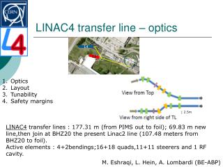
TTL1 Beam Line Geometry 100 m horizontal bending magnets injectionchicane magnet SPL end point H1 beam H2 V1 V2 point C vertical bending magnets PS2 meeting 12.03.2009 - TE/ABT/BTP
TTL1 Beam Line Geometry 100 m horizontal bending magnets injectionchicane magnet SPL end point H1 beam H2 V1 V2 point C vertical bending magnets → Design compatible with LP-SPL and HP-SPL → Maximum slope of 7.7% PS2 meeting 12.03.2009 - TE/ABT/BTP
TTL1 Beam Line Geometry SPS TT11 transfer line PS2 y (m) TT10 TTL1 transfer line point C TI 2 x (m) PS2 meeting 12.03.2009 - TE/ABT/BTP
Beam and Twiss Parameters SPL end point (Source: M. Eshraqi): Injection point (Source: W. Bartmann): PS2 meeting 12.03.2009 - TE/ABT/BTP
Optics Simulation Fodo lattice → 25 m cell length→ 90° phase advance per cell 2 matching sections PS2 meeting 12.03.2009 - TE/ABT/BTP
Optics Simulation PS2 meeting 12.03.2009 - TE/ABT/BTP
Optics Simulation PS2 meeting 12.03.2009 - TE/ABT/BTP
Quadrupole Families PS2 meeting 12.03.2009 - TE/ABT/BTP
Aperture Calculation x y beam envelope (m) s (m) PS2 meeting 12.03.2009 - TE/ABT/BTP
Trajectory Correction Scheme (on-going) correctors bending magnet • Quadrupole displacement errors: Gaussian distribution in x/y with s = 0.2 mm, cut at 3s • Dipole field errors: Gaussian distribution of deflection with s = 10 µrad, cut at 2s (→ relative field error of 5e-4) • Dipole tilt errors: Gaussian distribution with s = 0.2 mrad, cut at 4s • Monitor errors: Flat random distribution of ±0.5 mm in both planes BPMs quadrupoles Assumed errors: PS2 meeting 12.03.2009 - TE/ABT/BTP
Trajectory Correction: Results uncorrected: x: 1.4 mm rms y: 2.8 mm rms corrected: x: 0.013 mm rms y: 0.029 mm rms max. corrector strength: x: 5.7e-02 mrad y: 4.9e-02 mrad PS2 meeting 12.03.2009 - TE/ABT/BTP
Next Steps • More detailed study of the trajectory correction scheme • BI specifications • Magnet specifications • Momentum collimation • Space charge effects with ABP colleagues • Rebunching / phase rotation • Beam loss estimates/maps • Optimisation investigations (e.g. compacting bends?) PS2 meeting 12.03.2009 - TE/ABT/BTP