Download
1 / 1
10 likes | 101 Views
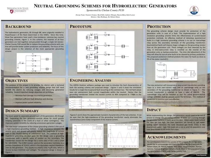
Neutral Grounding Schemes for Hydroelectric Generators Sponsored by Chelan County PUD Design Team: Gustavo Gomez, Brett Bell, Andrew Morgan, Basem Khoj, Kyle Lesser Mentors: Bert Hoffman, Dr. Robert Olson. Objectives. Background. Prototype. Engineering Analysis. Protection. Impact.

E N D
Neutral Grounding Schemes for Hydroelectric Generators Sponsored by Chelan County PUD Design Team: Gustavo Gomez, Brett Bell, Andrew Morgan, Basem Khoj, Kyle Lesser Mentors: Bert Hoffman, Dr. Robert Olson Objectives Background Prototype Engineering Analysis Protection Impact Acknowledgments The grounding scheme design must provide for protection of the generation units in case of a fault. The implementation of a high resistance grounding scheme limits the effectiveness of current-based protection methods. An effective method of detecting asymmetrical faults in a high resistance grounding scheme is to use an overvoltage relay across the secondary terminals of the grounding transformer. Asymmetrical faults will impress larger voltages on the grounding resistor than on the generation unit. These voltages are then detected by the relay. A time-overcurrent relay is installed on the neutral of the generation units as backup protection. The time dial adjustment of the relay will allow for out-of-zone faults to be cleared by primary protection. This proposed protection method protects the stator for faults as close as 2% of the stator neutral[1]. The hydroelectric generators, B5 through B8, were originally installed in Powerhouse-1 of the Rock Island Dam in the 1930’s. Since this time, these four generators have used a low-resistance, common-bus neutral grounding scheme, Figure 1. In this scheme, the neutrals of all four generators are tied together and grounded through a single 4𝛺 resistor. Chelan County PUD would like to replace the grounding scheme with one that will provide better system protection and reliability. The focus of this design project is the selection of the most appropriate grounding scheme. Figure 2: Proposed neutral grounding scheme design Figure 7: Protection system The purpose of the project is to provide the district with a technical recommendation for a new grounding scheme design that will most benefit the district by reducing outages and increasing generation reliability. Several important design objectives are as follows: The ASPEN Oneliner software package was used to simulate the fault characteristics of both the existing scheme and proposed design. Figures 3 and 4 show the simulation results for a single-line-to-ground fault occurring at the common bus. The red fault values seen are subtransient fault current magnitudes within the neutral. Notice that the grounding transformer limited the neutral current to 40A compared to 7788A in the existing scheme. The new protection will incorporate a new current transformer providing input to a time over-current relay and an overvoltage relay on the secondary of the grounding transformer as shown in Figure 7. The current transformer is selected to have a ratio of 400:5A. The overvoltage relay will be installed so that the entire ground-neutral voltage (240VAC) shall be present across the terminals. This method of protection is common and cost-effective. Figure 1: Existing grounding scheme for generators B5 through B8 • Minimize fault damage incurred by generators. • Maintain sufficient fault detection and clearing. • Improve power system reliability. [1]PrafullaPillai."Grounding and Ground Fault Protection of Multiple Generator Installations on Medium-Voltage Industrial and Commercial Power Systems—Part 3: Protection Methods," Kellogg Brown & Root, Inc.Houston, Texas, Working Group Rep.Feb. 2004. Figure 3: Existing grounding scheme – ASPEN Fault Simulation Figure 4: Grounding Transformer – ASPEN Fault Simulation Design Summary Figures 5 and 6 show the approximate transient characteristics of the two schemes. It can be seen that the high-impedance of the grounding transformer nearly eliminates the asynchronous (zero-state) component of the neutral current. While implementing this design, the generators would need to be out of service to change the grounding scheme. If water isn’t running through the generator turbines it backs up at the dam. When water levels behind the dam get too high, the Dam operators are forced to spill water. Spilling water increases the total dissolved gas levels (TDG) in the downstream water. High TDG levels are a risk to wild fish population and have been known to kill entire fish crops. The team opted to separately ground each of the generators, B5 through B8. Separating the four generator-neutrals allows for much greater relaying selectivity in the event of a fault or other contingency. This improves system reliability by reducing unnecessary generator outages. The next major component of the chosen grounding scheme is the use of a high-impedance grounding method. A high impedance between the neutral point and ground will greatly reduce the magnitude of current seen in the neutral during an unbalanced fault. The method of high-impedance grounding decided upon for the design uses a grounding transformer with a specific value of resistor on the secondary. The transformer chosen for the design has a turns ratio of 50:1 and is rated for 12kV/240V. The 0.49𝛺 resistor used on the secondary translates to a primary impedance of 1218 𝛺, which is the equivalent neutral impedance seen by the generator. This results in a nearly unity Xcg/R ratio, which is desired to best minimize over-voltages. The proposed design is shown in Figure 2. For contributions toward the success of this project, the design team would like to acknowledge and thank the following: Bert Hoffman, Dr. Robert Olsen, Dr. Patrick Pedrow, John Yates, SaugataBiswas, Ramon Zamora, CeemanBrightsonVellathurai, Dr. Mani V. Venkatasubramanian, the WSU School of EECS, and Chelan County PUD. Figure 6: Proposed Scheme – Transient Characteristic Figure 5: Existing Scheme – Transient Characteristic Team Bardeen