Download
1 / 37
370 likes | 526 Views
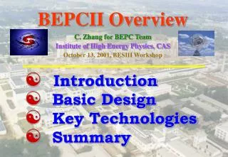
BEPCII Overview C. Zhang for BEPC Team Institute of High Energy Physics, CAS October 13, 2001, BESIII Workshop. Introduction Basic Design Key Technologies Summary. (1) Introduction. A brief description on BEPC Main parameters Operation and performance From BEPCI to BEPCII.

E N D
BEPCII OverviewC. Zhang for BEPC TeamInstitute of High Energy Physics, CAS October 13, 2001, BESIII Workshop • Introduction • Basic Design • Key Technologies • Summary
(1) Introduction • A brief description on BEPC • Main parameters • Operation and performance • From BEPCI to BEPCII
1.1 A Brief Description on BEPC • The Beijing Electron-Positron Collider (BEPC) was constructed (1984-1988) for both high energy physics and synchrotron radiation research. • The machine has been well operated for 12 years since it was put into operation in 1989. • The BEPC accelerator system consists of a 202-meter long linac injector, a 210-meter long beam transport line and a 204.4-meter circumference storage ring.
1.2 Main Parameters Beam Energy (E) 1.0 ~ 2.5 GeV Revolution frequency (fr) 1.247 MHz Lattice Type FODO + Low-b Insertions *x -function at IP (*x/ *y) 1.3/0.05 m Transverse Tune (x/y) 5.8/6.8 (Col. Mode) 8.72/4.75 (SR Mode) Natural Energy Spread (e) 2.64E 10-4 Momentum Com. Factor (p) 0.042 (Col. Mode) 0.016 (SR Mode) Hor. Natural Emittance (x0) 0.4@1.55 GeV, 0.076@2.2GeV(SR) mmmr RF Frequency (frf) 199.533 MHz Harmonic Number (h) 160 RF Voltage (Vrf) 0.6~1.6 MV Bunch Number (Nb) 1*1 (Col.), 60~80 (SR) Maximum Beam Current 50mA@1.55 GeV (Col.,) 130mA (SR) Luminosity 5 1030 cm-2 s-1@1.55 GeV, 11031 cm-2 s-1@2 GeV
1.3 Operation and Performance Start-up Fault Injection 6% 4% 12% BSRF MD 26% 10% BES 42%
Daily J/y operation of BEPC Period Days Beam time (hrs.) J/y events Lmax(1030cm-2 s-1) t(hrs) 99-00 142 2323 24 M 4 8-10 00-01 110 1900 22 M 5 8-10
The physics opportunity of BEPC calls higher luminosityBEPCII To collect some 109 J/y events and 108y′events in 4 years; Light hadron spectroscopy, charmed mesons and t at the thresholds; Hadron production mechanism, low energy QCD; Precision R values, ambiguous’ structures in 3.8-4.4 GeV; Searches: 1P1, c’, glueball, hybrids, exotic states; New physics: probing rare decay, LFV and CP violation from the decays of J/ and (2S); 1.4 From BEPCI to BEPCII
(2) The Basic Design • Strategy of Luminosity Upgrades • The double ring structure • Design Goals and Main Parameters • TheLattice and Dynamic Aperture • The Collective Effects • Beam Lifetime & Average Luminosity
2.1 Strategy of luminosity upgrades DR: multy-bunch kbmax~400,kb=1 93 Choose large ex & optimum param.: Ib=12mA, xy=0.04 Micro-b:by*=5cm 1~1.5 cm SC insertion quads Reduce impedance +SC RF sz=5cm ~1cm (LBEPCII/ LBEPCI)D.R.=(5/1.5) 93 12/20=186
BEPCI:Ib=20 mA, by*=5cm, kb=1,L=51030cm-2 s-1 @1.55GeV (1 1031cm-2 s-1 @2GeV )BEPCII=BEPCI+micro-b + Multibunch + Better SR performance
2.2 The double ring Structure RF SR RF + - e e IP
A large amount of excellent professional work has been accomplished leading to the Feasibility Study Report on BEPC II. As now proposed, BEPC II can be constructed either in a single ring or two-ring version, differing in expected performance and cost. • The committee is pleased that the luminosity goal of the BEPC II has been raised from the early proposed gain by a factor of ten to the single ring goal of 3-41032 cm-2sec-1 or the double ring goal of 11033cm-2sec-1. The committee considers these raised goals to be technically feasible and recommends the most aggressive approach consistent with the resources that can be made available.This implies a strong preference for the two-ring option. • The scientific environment in which BEPC II will have to operate has changed considerably from that in which BEPC I has a monopoly in this energy range. The now operating B-factories will accumulate extensive data, however with generally higher background, in this energy range and the recent decision by the Cornell University Laboratory of Nuclear Studies to move the operating range of its CESR collider into the tau-charm range to operate at a luminosity of about 31032 cm-2 sec-1 has major implications for the future of Chinese high energy physics. While the latter move attests to the continuing scientific importance of this field of inquiry, it should be noted that the CESR program in this energy range will commence several years sooner than is feasible for BEPC II. • The committee judges that the double ring design implies a lower risk in attaining its design luminosity in a brief commissioning time than does the single ring “pretzel” design. From the Report of International Review on BEPCII Feasibility Study
Model test of the double ring installation • No unsolvable problems are found for the transportation, installation, mounting and dismount of the magnets. • The existing monuments for survey and alignment will be covered by the inner ring magnets. New monuments will be fixed on the wall of the tunnel. • The antechamber of the positron ring needs to be carefully designed to fit the crucial space between two rings; • The cable system, the cooling-watersystem, the pressure-air system and others need to be rearranged.
2.5 Collective Effects2.5.1 Bunch Lengthening Vrf=1.5MV, |Z/n|eff=0.23, Ith = 21.4mA sz~sz0=1.1cm • |Z/n|0=4 0.2 • MAFIA computation & measurement • Bellows, kickers, separators, BPM’s, masks, connectors, valves, pumps, SR ports, IR
2.5.2 Coupled Bunch Instabilities • Beam cavity interaction(Nb=99, Ib=12 mA, using KEKB SC cavities) • Resistive wall instability x/y= 6.58/7.64,Nb = 99, Ib = 12mA, = 16.4ms; • Ion effects • Photo-electron cloud instability: Use antechamber for positron ring • Bunch feedback
2.2.3 Beam-beam effects • Head-on beam-beam effect: similar to BEPCI x=0.04 has been demonstrated • Parasitic beam-beam effect Dx10 sx andc=5.52 mrad • Horizontal crossing angle c (5.5-11)2 mrad(BEPCII), 2.32 mrad(CESR) 112 mrad(KEKB), 12.5 2 mrad(DAFNE) • Crossing angle+Parasitic collisions (Arcs & IR) More sophisticated simulation study.
2.2.4 Beam Lifetime and Average Luminosity Taking t =1.35 hrs., tf= 0.4 hr. and L0=11033 cm -2s-1, the optimized collision time is calculated as 1.0 hrs. and the maximum average luminosity is calculated as Lmax=0.51033 cm-2s-1. The top-off injection will further improve the average luminosity.
(3) Key Technologies • Injector upgrading • 500 MHz SC RF System • SC Micro-b Quads and IR • Low Impedance Kickers • Vacuum System • Power Supply System • Instrumentation Upgrade • Control Upgrade
3.1 Injector upgrading • Basic requirement: • Higher intensity: positron injection rate 50 mA/min.; • Full energy injection with E=1.55 ~ 1.89 GeV; • To enhance the current and energy of the electron beam bombarding the target and to reduce the beam spot; • To design and produce a new positron source and to improve its focusing; • To increase the repetition rate from present 12.5 Hz to 50 Hz. • To consider multi-bunch injection (fRF/fLinac=7/40);
3.2 500 MHz SC RF System • Basic requirement • Sufficient RF voltage for short bunches. • Sufficient high RF power. • Suppressing the instabilities related to RF system. • Stable and reliable RF system • Strategy:to take advantage of collaboration with SSRF, Cornell and KEK and to apply the existing industrial technology.
Options of 500 MHz SC RF Cavity CESR-type Cavity (ACCEL)KEKB-type Cavity (Mitsubishi ) • IHEP RF group will work at optimization of the cavity design, trace the manufacture and be trained to maintain the SC RF system.
The SC magnets and IR Design • Space and dimension • Installation and alignment • Solenoid and its compensation • Magnet leakage field • Background and masking • Cryogenics • ……
Magnetic field distribution in the kicker 3.4 Low Impedance Kickers • The study has shown that the kickers are one of major sources of impedance, where single turn air coils are located inside vacuum chamber of the kickers. • The new kickers of BEPCII impose the ferrite magnet outside the vacuum with ceramic beam pipes so that the impedance problem is avoided. • The pipes are with resistive coating on its inner surface.
3.5 Vacuum System • The BEPCII poses two challenges to the vacuum system, one is vacuum pressure, other is the impedance. • The dynamic vacuum at a high beam current should satisfy the requirements of sufficient beam lifetime, low background in the detector. The design vacuum pressure is 510-9 Torr in the arc and 510-10 Torr in the IR. • To reduce the impedance, the vacuum chamber should be as smooth as possible. Some of the chamber structures will be shielded, some will be replaced with new designed components.
3.6 Power Supply System • The superconducting insertion quadruple magnets for micro-b need to be powered with new power supplies. • The pretzel scheme need more independent power supplies, namely 34 for quadruples and 18 for sextupoles. In the double-ring case, this numbers are about doubled. • In order to mount the additional power supplies in the existing rooms, the new power supplies should be compact by using improved technology.
Beam Position Monitor Bunch Current Monitor Beam Feedback System Synchrotron Light Monitor IP beam position control 3.7 Instrumentation Upgrade
3.8 Control System: switch from BEPCI to BEPCII WS console Ethernet PC subsystems VAX 4500 Injection Beam diagnostic Linac CAMAC PS, Vacuum, RF
Collaboration on BEPCII Accelerators • Linac: SLAC, KEK, INFN • SCMicro-bquadruples: BNL, KEK • SC RF cavities: Cornell, KEK • Impedance study: LBNL • Beam Instrumentation: CERN, SLAC • Under discussion: BINP and other labs • Domestic institutions: SSRF, Tsinghua, PU •
Budget and Schedule • The budget of the BEPCII project is estimated as about 600 million RMB for both accelerators and detector. • The project is expected to finish in 3-4 years after its approval.
(4) Summary • BEPC has been well operated with many exciting HEP and SR results for 12 years since it was put into operation in 1989. • BEPCII is proposed as micro-b plus multibunches with two rings and its design luminosity is order of magnitude higher than present BEPC in energy range of J/y and y’. • Some key technologies need to be developed to achieve the goal of BEPC II. • The international collaboration and contribution will be promoted in order to accomplish this challenging and exciting project on schedule and budget.