Download
1 / 49
520 likes | 676 Views
Cache Memory. Historically, CPUs have always been faster than memories. In order to have a memory as fast as a CPU it must be located on the CPU chip. This makes the chip bigger and more expensive.

E N D
Cache Memory • Historically, CPUs have always been faster than memories. In order to have a memory as fast as a CPU it must be located on the CPU chip. This makes the chip bigger and more expensive. • By combining a small fast memory with a large slow memory, we can get the speed (almost) of the fast memory for the price of the slow memory. The fast memory is called a cache.
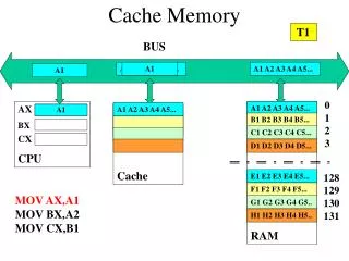
Cache Memory • Basic idea: most heavily used memory words are kept in the cache. When a memory word is required, the CPU first looks in the cache. If the word is not there, it looks to main memory. • In order to be successful, a large percentage of the words searched must be in the cache. We can ensure this by exploiting the locality principle. When a word is referenced, it and some of its neighbors are brought into the cache, so next time it can be accessed quickly.
Cache Memory • Let c be the cache access time, m the main memory access time, and h the hit ratio (fraction of references satisfied out of the cache). Then the mean access time is: c + (1 - h) m • As h approaches 1, all references can be satisfied out of cache and the access time approaches c. On the other hand, as h approaches 0, the access time approaches c + m.
Cache Memory • Using the locality principle, main memory and cache are divided up into fixed-size blocks. When referring to the cache, these blocks are called cache lines. When a cache miss occurs, the entire cache block is loaded. • Instructions and data can either be kept in the same cache (unified cache) or in separate caches (split caches). • There can also be multiple caches (on chip, off chip but in the same package as the CPU, and farther away).
Cache Memory • The cache is logically between the CPU and main memory. Physically, there are several possible places it could be located.
Memory Packaging and Types • From the early days of semiconductor manufacture until the early 1990s, memory was manufactured, bought, and installed as single chips. At present, a different arrangement is often used. A group of chips (typically 8 or 16) is mounted on a printed circuit board and sold as a unit. This unit is called a SIMM (Single Inline Memory Module) or DIMM (Dual Inline Memory Module), depending on whether it has a row of connectors on one or both sides of the board.
DIMM Modules • Top view of a DIMM holding 4 GB with eight chips of 256 MB on each side. The other side looks the same.
SIMM and DIMM Modules • A typical SIMM configuration might have 8 chips with 4MB each on the SIMM for a total of 32MB. • The first SIMMs had 30 connectors and delivered 8 bits at a time. Later SIMMs had 72 connectors and delivered 32 bits at a time. At present, DIMMs are the standard way for memory to be packaged. DIMMs can deliver 64 data bits at once. A physically smaller DIMM, called an SO-DIMM (Small Outline DIMM) is used in notebook computers.
Secondary Memory • No matter how fast main memory is, it is always too small. • The traditional solution is a memory hierarchy in which we have small amounts of fast, expensive memory, and increasingly larger amounts of slower, less expensive memory. The storage capacity increases the further we go down the hierarchy.
Memory Hierarchies • A five level memory hierarchy.
Magnetic Disks • A magnetic disk consists of one or more aluminum platters with a magnetizable coating. They are typically 3 to 12 cm in diameter. • A disk head floats over the surface of the disk. The disk head can magnetize the surface or read the bits previously stored. • The circular sequence of bits written as the disk makes a complete rotation is called a track. Each track is divided into fixed-length sectors.
Magnetic Disks • Sectors typically consist of a preamble (for head synchronization), followed by 512 data bytes. Following the data is an Error-Correcting Code, either a Hamming code, or more commonly, a code that can correct multiple errors called a Reed-Solomon code. Between consecutive sectors is a small intersector gap. • Disk arms can move to different radial distances from the spindle. At each distance, a track is written.
Magnetic Disks • A portion of a disk track. Two sectors are illustrated.
Magnetic Disks • In order to achieve high quality, most disks are sealed at the factory to prevent dust from entering. These disks are called Winchester disks. • Most disks consist of multiple platters stacked vertically. Each surface has its own arm and head, but they move together. The set of tracks at a given radial position is called a cylinder. • Disk performance depends on seek time (moving the arm to the right cylinder) and rotational latency (spinning the disk to the right sector).
Magnetic Disks • A disk with four platters.
Magnetic Disks • A disk with five zones. Each zone has many tracks.
Magnetic Disks • As disks rotate, they get hot and their physical geometry changes. Thus, periodically they undergo thermal recalibration (the heads are forced all the way in or out). • Special audio-visual disk drives do not have these recalibrations since multimedia applications require a constant bit stream. • Each drive has an associated disk controller, a chip that controls the drive. The disk controller accepts commands from software, detects bad sectors, buffers data, etc.
IDE Disks • Early PCs had a disk controller on a plug-in card. The OS read from and wrote to the disk by putting parameters in CPU registers and then calling the BIOS (Basic Input Output System), located in the PCs ROM. The BIOS then issued the machine instructions to load the disk controller registers and initiate transfers. • By the mid 1980s, the controller was no longer on a separate card, but closely integrated with the drive. These drives were called IDE (Integrated Electronic Drives).
IDE Disks • BIOS calling conventions were not changed for backward compatibility. Sectors were addressed by giving head, cylinder, and sector numbers. • 4 bits for the head, 6 bits for the sector, and 10 bits for the cylinder give 1,032,192 possible sectors or a maximum drive capacity of 504 MB (note that sectors are numbered starting at 1, not 0). • In order to get around these limits, the disk controllers began to use different geometries that couldn’t be addressed by the BIOS.
IDE Disks • IDE drives evolved into EIDE drives (Extended IDE) which support an addressing scheme called LBA (Logical Block Addressing) which numbers sectors from 0 to 228 - 1. The controller then converts LBA addresses to head, sector, cylinder addresses, but there is no 504 MB limit. • EIDE controllers can also control four drives instead of two, have a higher transfer rate, and have the ability to control CD-ROM drives.
EIDE Drives • Successors to EIDE were called ATA-3 and ATAPI-4 • Still had a limit of 22829 bytes (128 GB) • Subsequently, ATAPI-6 had a LBA size of 48 bits (max disk size of 128 PB). • Speed increased from 16.67 MB/sec with EIDE to 100 MB/sec with ATAPI-6 • ATAPI-7 uses serial ATA with a smaller drive connector and lower power consumption
SCSI Disks • SCSI disks are not different from IDE disks in terms of how their cylinders, tracks, and sectors are organized, but they have a different interface and much higher transfer rates. • SCSI is more than a hard disk interface, it is a bus to which a SCSI controller and up to seven devices (hard disks, CD ROMs, scanners, etc.) can be attached. • Each SCSI device has a unique ID, from 0 to 7 (15 for wide SCSI). Each device has two connectors, one for input and one for output.
SCSI Disks • Cables connect the output of one device to the input of the next, in series. The last device in the series must be terminated to prevent reflections from interfering with other data. Typically, the controller is on a plug-in card. • SCSI controllers and devices can operate either as initiators or as targets. Usually, the controller issues commands to the disks and peripherals. • Multiple SCSI devices can run at once using bus arbitration. IDE and EIDE allow only one active device at a time.
SCSI Disks • Some possible SCSI parameters.
RAID • Parallel processing is increasingly used to speed up CPU performance. Likewise, parallel I/O can be used to speed up I/O. • RAID (Redundant Array of Inexpensive Disks) is a set of six specific disk organizations that can be used to improve disk performance, or reliability, or both. • Most RAIDs consist of a RAID SCSI controller plus a box of SCSI disks that appear to the OS as a single large disk. No software changes are required to use the RAID.
RAID • The data in a RAID are distributed over the drives, to allow parallel operation. Several schemes were devised by Patterson and are known as RAID level 0 through RAID level 5. • RAID level 0 stripes data over multiple drives in round robin fashion. In this way, a block of data can be read from multiple drives, working in parallel. This works best when data is requested in large chunks. The controller must coordinate the request and issue the individual requests to the disks.
RAID • RAID level 0 is less robust than using a single disk, since the failure of any disk leads to failure for the RAID. • RAID level 1 is a true RAID. It duplicates all the disks so that there are four primary and four backup disks. On a write, a strip is written twice. On a read, either copy can be read. Fault tolerance is excellent. • RAID level 2 works on a word basis, possibly even a byte basis. All drives must be synchronized and there must be a large number of drives.
RAID • The Thinking Machine CM-2 used this scheme, taking a 32-bit word and adding 6 parity bits to form a 38-bit Hamming word, plus an extra bit for word parity. Each word was spread over 39 disks. • RAID level 3 is a simplified version of level 2. A single parity bit is computed for each data word and written to a parity drive. As in level 2, the drives must be exactly synchronized.
RAID • RAID levels 4 and 5 work with strips again, with parity. RAID level 4 writes a parity strip (computed from the strips on each of the other disks) on an extra drive. If a drive crashes, the lost bytes can be recomputed from the parity drive. • RAID level 5 distributes the parity bits uniformly over all the disks so that the parity drive does not become a bottleneck. This makes recovery more complex, however.
RAID • RAID levels 0-2. Backup and parity drives are shown shaded.
RAID • RAID levels 3-5
Solid-State Disks • SSDs don’t actually contain disks or moving parts • They have interfaces compatible with the block I/O access of traditional hard drives • Use NAND-based flash memory which maintains data without power • 7-8 times more expensive per bit than HDDs • Hybrid drives with both disks and SSD caches are available as well
Solid-State Disks • A flash memory cell.
CD-ROM • Optical disks are attractive storage devices since they have much higher recording densities than magnetic disks. • Audio CDs code data by burning pits into the surface of the CD. The unburned areas between the pits are called lands. The data is recorded on a spiral groove. The CD is then covered with a protective material. The data on the CD can then be read with a laser. A pit/land or land/pit transition records a 1, and its absence is a 0.
CD-ROM • Recording structure of CD or CD-ROM
CD-ROM • In 1984, the CD-ROM standard for storing computer data on CDs was published. CD-ROMs were mechanically and optically compatible with audio CDs. • Error correction/detection coding was added using 14-bit symbols to encode one data byte. • 42 consecutive symbols form a 588-bit frame. Each frame contains 192 data bits. The remaining 396 bits are for error correction and control.
CD-ROM • 98 frames are combined into a CD-ROM sector with a 16-byte preamble and a 288-byte error-correcting code. • Single-bit errors are corrected at the lowest level, short burst errors at the frame level, and any residual errors at the sector level. • CD-ROMs are much slower than high-performance magnetic disks. • The CD-ROM file system is called High Sierra (IS 9660) and can be read on many different computers.
CD-ROM • Logical data layout on a CD-ROM
CD-R Disks • CD-R (CD-Recordable) disks allow for data to be written (once) to a CD. These disks use gold rather than aluminum for the reflective layer and rather than pits and lands, use a layer of dye which can be affected by the CD-R laser to simulate the pits and lands. • Multisession CDs allow for incremental writing (don’t write the contents at the start of the disk). • CD-RW (CD-ReWritable) uses an alloy for the recording layer rather than dye. CD-RW blanks are more expensive than CD-R blanks.
CD-R Disks • Cross section of a CD-R disk and laser (not to scale). A CD-ROM has a similar structure, except without the dye layer and with a pitted aluminum layer instead of a reflective layer.
DVD • CD-ROM disks do not have a high enough capacity to store digital videos, so a new standard reflecting technology advances of the last 20 years called DVD (Digital Versatile Disk) has been introduced. The basic design is the same as CDs, but with: • smaller pits • a tighter spiral • a red laser • This increases the capacity to 4.7 GB, enough to hold 133 minutes of MPEG-2 video.
DVD • The red laser means that in order to read both DVD and CD disks, drives must have a second laser. • In order to increase capacity, double-sided and dual-layer formats have been defined. • The dual-layering has a reflective layer at the bottom, topped with a semireflective layer. Depending on where the laser is focused, it bounces off one layer or the other. • Double-sided disks are made by gluing two disks together, back-to-back.
DVD • A double-sided, dual-layer DVD disk.
Blu-Ray • The next generation optical disk format is called Blu-Ray • Uses blue, rather than red, laser • Smaller pits and lands • Single sided storage of 25 GB, double sided at 50 GB • 4.5 MB/sec data rate • To be used for recording HDTV