Download
1 / 12
120 likes | 272 Views
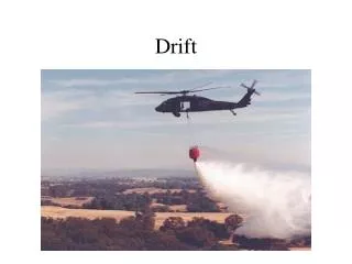
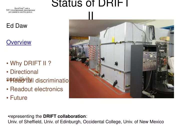
Why DRIFT II ?. Directional sensitivity. Head tail discrimination. Readout electronics. Future. Ed Daw. Status of DRIFT II. Overview. representing the DRIFT collaboration : Univ. of Sheffield, Univ. of Edinburgh, Occidental College, Univ. of New Mexico. Why DRIFT II ?.

E N D
Why DRIFT II ? • Directional sensitivity • Head tail discrimination • Readout electronics • Future Ed Daw Status of DRIFT II Overview • representing the DRIFT collaboration: • Univ. of Sheffield, Univ. of Edinburgh, Occidental College, Univ. of New Mexico
Why DRIFT II ? First detection - compact solid or liquid target ‘counting detectors’, EVENT RATE vs. ENERGY - like Zeplin III, for example. BUT - nature is unkind - sources of background at all rates. Distinguishing WIMP signals from background: • Rate vs. energy. in different targets. • Modulation of rate vs. energy • Modulation of direction of incidence Not easy ! Even in a diffuse gas, recoil tracks are short. DRIFT II is prototype modules built to develop this technology. Plus - usual menagerie of problems with dark matter detectors - background sources of nuclear recoil, gamma discrimination, radon, etc.
ELECTRIC FIELD LINES 2mm ANODE WIRES GRID WIRES • 1.5 m3 time projection chambers containing 40 torr of CS2 with MWPC readout • Target mass is 120g of sulphur. Readout CATHODE 35kV GRID 3kV Close to anode wires in the high electric field: 1cm AVALANCHE INCIDENT WIMP Ions drift back towards grid and drift region, induce voltage pulses on grid and anode X and Y track information from channel hits Z track information from pulse shape on wires NUCLEAR RECOIL, 1-10s of keV recoil kinetic energy
Energy calibration 5.9 keV X-rays from 55Fe source fully contained in the detector. • Frequency domain filtering using FFT/IFFT to remove noise • Savitzky-Golay smoothing to remove high frequency noise • Identify tracks for multi-wire hits • Histogram sum of areas of hits identified with track. D. Muna, Ph.D. thesis, Sheffield, 2008, section 5.1 - paper in preparation. anode pulse areas summed over channels (LSB-ns)
[ PRELIMINARY ] A 252Cf neutron source was placed on the three principle axes of a DRIFT II module. Figure below shows histograms of the three components of the reconstructed track range for events passing selection cuts. Cuts select events having recoil energies of greater than 250 keV. Directional sensitivity [grid wires are vertical, anode wires are horizontal]
LEFT DRIFT CHAMBER RIGHT DRIFT CHAMBER [ PRELIMINARY ] Track head-tail discrimination 1000 NIPs (number of ion pairs) is 47 keV for sulphur recoils.
[ PRELIMINARY ] Radon Progeny Recoils DRIFT II sees an excess of background events attributed to recoils of 210Pb plated out on the detector. A likely region for build-up of 210Pb is on the cathode wires. Before cleaning After cleaning Johanna Turk ( University of New Mexico ) Mark Pipe ( University of Sheffield ) Kirill Pushkin ( Occidental College ) factor of 16 reduction in background rate Next step is to apply the same cleaning procedure to the MWPC grid and anode wires. Scheduled for July.
Readout Electronics Development PROTOTYPE MODULE Aim of new electronics: LAYOUT PER CHANNEL • To reduce noise background from the grid and anode planes. • To lower the energy threshold. • To improve trigger efficiency for slower pulses. • To improve track reconstruction, including timing.
CURRENT CATHODE READOUT 1 2 3 4 5 6 7 8 SUM [ PRELIMINARY ] Reduction in grid readout noise Oscillatory component appears at 50 kHz in the digitized data. Disappearance of this line in data taken through the new electronics implies that this line is aliased down from above the Nyquist cutoff of 500 kHz.
Conclusions During the last six months, DRIFT II has demonstrated : • Extraction of directional information and head tail discrimination for nuclear recoil calibration data. • Reduction of nuclear recoil background by a factor of 20 through nitric acid etch of the cathode wires • Reduced energy threshold and lower noise with improved electronics. Operations planned during the next six months : • Nitric acid etch of the MWPC wire planes for further background reduction • Fabricate and commission 36 channels of redesigned electronics • Installation of lower noise electronics for lower threshold operation and greater sensitivity to tracks having lower dE/dx. • Study of the sensitivity of DRIFT to X rays • Study of directional information at lower recoil energy
Expected nuclear recoil ranges sulphur: carbon: